August 2015
Instruction Book
IB02707112E
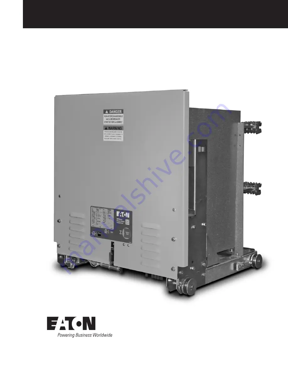
50/75VCPW-VSR
Breaker To Vacuum Starter Replacement Unit
50VCPW-VSR 350 390A Shown
Supersedes May 2014Effective
Page 1: ...August 2015 Instruction Book IB02707112E 50 75VCPW VSR Breaker To Vacuum Starter Replacement Unit 50VCPW VSR 350 390A Shown Supersedes May 2014 Effective ...
Page 2: ... WARRANTIES OF FITNESS FOR A PARTICULAR PURPOSE OR MERCHANTABILITY OTHER THAN THOSE SPECIFICALLY SET OUT IN ANY EXISTING CONTRACT BETWEEN THE PARTIES ANY SUCH CONTRACT STATES THE ENTIRE OBLIGATION OF EATON THE CONTENTS OF THIS DOCUMENT SHALL NOT BECOME PART OF OR MODIFY ANY CONTRACT BETWEEN THE PARTIES In no event will Eaton be responsible to the purchaser or user in contract in tort including neg...
Page 3: ...SAFETY CODES SAFETY STANDARDS AND OR REGULATIONS AS THEY MAY BE APPLIED TO THIS TYPE OF EQUIPMENT MUST BE STRICTLY ADHERED TO THESE VACUUM STARTER REPLACEMENT UNITS ARE DESIGNED TO BE INSTALLED PURSUANT TO THE AMERICAN NATIONAL STANDARDS INSTITUTE ANSI SERIOUS INJURY INCLUDING DEATH CAN RESULT FROM FAILURE TO FOLLOW THE PROCEDURES OUTLINED IN THIS MANUAL This product was manufactured by Eaton Corp...
Page 4: ...ted as Cutler Hammer and or Eaton WARNING SATISFACTORY PERFORMANCE OF THESE UNITS ARE CONTINGENT UPON PROPER APPLICATION CORRECT INSTALLATION AND ADEQUATE MAINTENANCE THIS INSTRUCTION BOOK MUST BE CAREFULLY READ AND FOLLOWED IN ORDER TO OBTAIN OPTIMUM PERFORMANCE FOR LONG USEFUL LIFE OF THE UNITS IT IS FURTHER RECOMMENDED THAT THE INSTALLATION BE PERFORMED BY A EATON CORPORATION TRAINED ENGINEER O...
Page 5: ... Existing Breaker Rated Continuous Current at 60 Hz Amps A B C D E F G H I J K 50VCPW VSR 250 230A 390A 29 44 29 12 10 00 29 81 12 00 13 63 27 80 29 56 2 25 20 88 24 63 50VCPW VSR 350 230A 390A 31 44 29 12 10 00 29 94 12 00 13 63 27 80 29 56 2 25 20 88 24 63 75VCPW VSR 500 230A 390A 29 44 29 12 10 00 29 81 12 00 13 63 27 80 29 56 2 25 20 88 24 63 D F E B C C A H G K J I ...
Page 6: ... any maintenance Failure to do so could result in electrical shock leading to death severe personnel injury or property damage Do not work on a unit with the secondary test coupler engaged Failure to disconnect the test coupler could result in an electrical shock leading to death personnel injury or property damage Do not work on a closed unit The main contacts should be open before working on the...
Page 7: ...ontact Wear Gauge Optional item used to check contact wear Style 5259C11H01 See Section 5 Racking Handle The original VCP W racking handle is used to assist in moving the MV VSR into and out of the cell Lifting Yoke Optional lifting device that can be used to install a VSR into upper compartment of VCP W switchgear Style 94M7103G99 3 2 HANDLING WARNING DO NOT USE ANY LIFTING DEVICE AS A PLATFORM F...
Page 8: ...t falling objects excessive moisture etc must be provided Containers should be arranged to permit free circulation of air on all sides and temporary heaters should be used to minimize condensation Moisture can cause rusting of metal parts and deterioration of high voltage insulation A heat level of approximately 400 watts for each 100 cubic feet of volume is recommended with the heaters distribute...
Page 9: ...cement Unit EATON CORPORATION www eaton com Figure 3 3 Front External View of 50VCPW VSR Front External View 1 Lifting Point 4 Push To Open Button 7 Lift Pull Handle 2 Extension Rail Interlock 5 Main Contact Status 8 Code Plate 3 Ground Contact 6 Starter Operations Counter 2 3 1 4 5 6 7 8 ...
Page 10: ... 75VCPW VSR BreakerTo Vacuum Starter Replacement Unit EATON CORPORATION www eaton com Figure 3 4 Rear External View of 50VCPW VSR Rear External View 1 Fuse 3 Phase Barrier 5 Primary Disconnects 2 Lifting Point 4 Extension Rail Interlock 2 1 3 4 5 5 ...
Page 11: ...closing circuit which remains made while the contactor is being racked between the Test and Connected positions Consequently it prevents the starter from closing automatically even though the control switch close may have been made while the starter is racked to the connected position When the close contact is made the MX closes the starter If the close contact is maintained after the starter clos...
Page 12: ...xiliary Contacts 12 Optional Auxiliary Contacts 6 Coil Control Board Terminal Block 13 Stop Assembly 7 Axial Magnetic Coil 3 SL400 Only 14 Base Plate SL Back View Major Components 1 Rear Mounting Holes 2 5 Upper Terminals 3 2 Shunt Supports 6 6 Lower Terminals 3 3 Coils 2 7 Locknut For Return Spring Bolt 4 Coil Mounting Angle 1 2 4 3 5 6 7 8 9 10 11 12 13 14 1 2 4 3 5 6 7 13 b 22 8 b 17 10 b 15 7 ...
Page 13: ...t be wired in parallel with the a contacts on the Electro MOC The original b contacts must be wired in series with the b contacts on the Electro MOC It is suggested that polarized voltages should not be used on adjacent contacts This is because of the remote possibility of flashover during transition between adjacent contacts especially at higher DC ratings or in highly inductive circuits Further ...
Page 14: ...tarters are made of glass polyester They are all easily removed for access to the fuses Table 4 2 Electro MOC Contact Ratings Contact Circuit Volts Short Time Rating Amps Continuous Rating Amps Interruptive Rating Amps Resistive Inductive 125Vdc 60 30 Single Contact 5 2 Double Contact 10 5 250Vdc 60 30 Single Contact 3 1 Double Contact 5 2 120Vac 60 30 Single Contact 20 20 Double Contact 30 30 240...
Page 15: ... the racking device is to move the VSR between the TEST and CONNECTED positions For the VCPW VSR the device is a drive screw and drive nut Although the device is mounted in the switchgear compartment a brief description here will help understand the operation For additional information on the insertion and removal of a VSR from its compartment refer to the insertion and removal sections in this ma...
Page 16: ...H IN SECTION 2 NOT FOLLOWING THE PROCEDURE MAY RESULT IN INCORRECT STARTER OPERATION LEADING TO DEATH BODILY INJURY AND PROPERTY DAMAGE When the starter is first commissioned into service and each time the starter is returned to service it should be carefully examined and checked to make sure it is clean and operating correctly 5 2 EXAMINATION FOR DAMAGE Examine the starter for loose or obviously ...
Page 17: ...ltage for one minute Repeat for the remaining phases Successful withstand indicates satisfactory insulation strength of the primary circuit Open the starter Connect the high potential lead of the test machine to one of the poles of the starter Connect the remaining poles and starter frame to ground Start the machine with output potential at zero and increase to the test voltage Maintain the test v...
Page 18: ... BE INSERTED INTO THE INTENDED STRUCTURE WARNING ARC FLASH INCIDENCES WITH MV SWITCHGEAR CAN OCCUR DURING THE PROCESS OF INSERTING AND REMOVING VSR UNITS IN SWITCHGEAR CUBICLES IT IS STRONGLY RECOMMENDED THAT PROPER PPE PERSONAL PROTECTIVE EQUIPMENT BE WORN BY PERSONNEL WHO RACK UNITS USING THE MANUAL RACKING HANDLE OR THE ROTARY RACKING HANDLE EATON CORPORATION PROVIDES A UNIVERSAL REMOTE POWER R...
Page 19: ...k with the structure mounted racking shaft Figure 5 9 Turn the racking in crank in a clockwise direction and the VSR will move slowly toward the rear of the structure When the VSR reaches the CONNECTED position it will become impossible to continue turning the racking in crank The CONNECTED position will also be indicated by a red flag indicator just below the racking device If a spin free racking...
Page 20: ... 8 Install the bolt securing the vacuum interrupter to the upper terminal do not tighten 9 Install bolt and shunt supports securing lower terminal to housing Figure 6 6 When tightening insure laminated shunt is straight and shunt supports are in the correct position 10 Tighten bolt securing vacuum interrupter to upper terminal while holding bottle wrench on upper vacuum interrupter stem Torque to ...
Page 21: ...applied the contactor should close cleanly When power is removed the moving armature should securely contact the stop assembly 6 3 Control Board Check and Replacement To verify the output of the control board apply rated control voltage to terminals one and two WARNING VERIFY THAT THE APPLIED POWER CANNOT BE FED BACK INTO ANY CPT OR OTHER CIRCUIT WHICH MAY GENERATE DANGEROUS VOLTAGES Using a stand...
Page 22: ...the coil has the proper resistance connect an ohmmeter across the coil leads where they are connected to the bridge rectifier Refer to Table 6 1 for the correct impedance for the different voltage coils If the coil impedance is not within the range in Table 6 1 it must be replaced Follow the steps below for replacement 1 Remove latch control wires from terminals 7 8 on contactor coil control board...
Page 23: ...ALLATION 1 Remove the existing roller bracket from the contactor moving armature if one is attached 2 Secure the new roller bracket and bearing assembly with two 6mm x 25mm bolts with lock washers and torque to 85 in lb 9 6 N m Insure that the side flanges of the roller bracket are parallel with the end of the armature plate Note If bolts longer than 25mm are used they will extend through the arma...
Page 24: ...WER TO CONTACTOR COIL IF VOLTAGE IS BACK FED INTO A TRANSFORMER HIGH VOLTAGE WILL BE GENERATED ON THE TRANSFORMER PRIMARY HIGH VOLTAGE CAN CAUSE SERIOUS INJURY OR DEATH 6 Apply force to latch assembly sliding cam towards roller bearing and tighten four mounting bolts through contactor baseplate Torque to 200 in lb 22 6 N m 7 Release the latch by depressing the latch release tab on the latch assemb...
Page 25: ...s clear barrier in place and can be lifted straight up for access to the fuse hardware Figure 7 1 2 To remove the side phase barrier for access to the outer fuse lift the phase barrier straight up and out of the notched retaining slots Figure 7 2 3 Remove the hardware securing the fuse from the rear of the VSR unit and retain for attaching the replacement fuse Figure 7 3 4 Remove the hardware secu...
Page 26: ... Part Number Description 2147A58G02 Vacuum Interrupter Assembly for SL 160 200 320 400 2147A58G03 Coil Control Board 2147A58G04 Auxiliary Contact Kit 2NO 2NC 2147A58G05 Auxiliary Contact Kit 3NO 3NC for Latched Contactor 2147A58G11 Dual Coil Assembly all voltages 2147A58G14 Stop Assembly 2147A58G22 Return Spring Assembly 2147A58G25 24vDC Latch Coil with Rectifier 2147A58G27 110 120vAC 125vDC Latch...
Page 27: ...27 Instruction Book IB02707112E August 2015 50 75VCPW VSR BreakerTo Vacuum Starter Replacement Unit EATON CORPORATION www eaton com ...
Page 28: ...ior Avenue Cleveland OH 44114 USA Eaton com 2014 Eaton Corporation All Rights Reserved Printed in USA Publication No IB02707112E August 2015 Eaton is a registered trademark of Eaton Corporation All trademarks are property of their respective owners ...