9
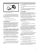
Spirolox Ring (31)
Hooked Tool
Figure 6. Removing Spirolox Ring
10. Pull the shaft group (24 through 26) from the body
(29). If the bearing (25) or shaft (26) needs replacement,
remove retaining ring (24) and press the bearing off the shaft
with an arbor press. Apply pressure to the inner race of the
bearing during removal.
11. Remove washer (27) from body.
12. Drive the shaft seal (28) out of body (29).
D. Cleaning 21.
All parts must be thoroughly cleaned and kept clean during
inspection and assembly. Contamination in the unit will
cause excessive wear, leakage and decreased service life.
Use a commercial solvent which is compatible with the
system fluid. Thoroughly clean all parts. Drying parts with
compressed air after cleaning is not recommended unless
the air is completely filtered to remove water and
contamination.
E. Inspection, Repair & Replacement
Check that all internal passages are clean and unobstructed.
Examine all mating surfaces for nicks and burrs. Check
locating pins and holes for wear and burrs. Check the
condition of threaded parts and threaded holes. Check all
retaining ring recesses. Minor burrs can be removed with an
India stone. Replace any part that shows wear or damage.
The following parts are subject to special attention.
1. Cartridge Kit (11). In order to obtain maximum
overhaul life of the pump, a complete cartridge kit should be
installed if wear or scoring is noticed during the following
steps.
a. Inspect the mating surfaces of the rotor (20),
outlet support plate (22) and inlet support plate (17).
b. Inspect the vanes and intra-vanes (21) for burrs,
wear and play in the rotor (20) slots. The intra-vanes should
not bind in the vanes. Remove minor burrs with an India
stone.
c. Inspect bushing for wear and scoring. Wear on
one side indicates that the pump and drive motor were not
aligned. See Figure 4.
2. Check bearing (25) for wear, looseness and pitted or
cracked races.
3. Inspect the seal and bushing mating surfaces on
shaft (26) for scoring and wear. Replace the shaft if marks
cannot be removed by light polishing.
F. Assembly
Refer to parts and service drawing listed in Table 1 for
replacement parts. Always replace old seals with new seals
when overhauling a unit. If a cartridge kit needs replacing,
new seals are included in the cartridge kit.
Apply a light film of hydraulic fluid to all component parts to
facilitate assembly and provide initial lubrication. Install parts
in reverse order of disassembly. See Figure 8.
1. Install shaft seal (28) into body (29) so that the
spring in the seal faces the inside of the pump. Press the
shaft seal into the body. Use shaft seal tool shown in Figure
5 and an arbor press.
2. Install washer (27) into body.
3. If required, press bearing (25) on to shaft (26) and
secure with retaining ring (24).
4. Recheck shaft key way for nicks and burrs that could
cut the shaft seal. Remove burrs. Thoroughly lubricate the
key way end of shaft and shaft seal lip with hydraulic oil.
Carefully install shaft group (items 24 through 26) through
the seal and into body (29). Spread the spirolox ring (23) and
feed it into the groove located behind the bearing. This will
secure the shaft group within body (29).
5. Assembly sealing ring (14) into body (29).
6. If a new cartridge kit is required, install new cartridge
kit (11) on the shaft and into the body (29). If cartridge kit
assembly is required, assemble in the reverse order of
disassembly. During assembly, note the following
precautions;
a. Make sure the rotation arrows on ring (19) and
rotor (20) point in the direction of rotation.
b. Be certain the sharp edges of vanes (21) lead in
direction of pump rotation. See Figure 7.
c. Make sure “O” ring (12) and back-up ring (13) are
positioned correctly as shown on Figure 8.
7. Apply a small amount of hydraulic fluid on threads of
two screws (16). Thread the screws into cartridge kit. Install
cartridge kit (11) on the shaft and into body (29).


