February 2017
Instruction Book
IB182017EN
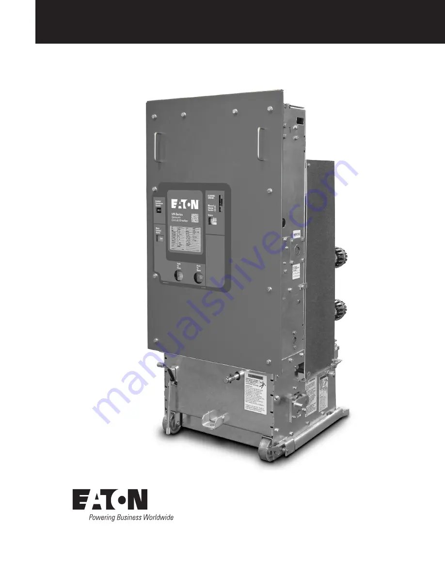
5kV, 7.5kV, & 15kV DHP-VR
Replacement Circuit Breaker
Supersedes I.B. 6513C80GEffective
5kV DHP-VR 1200A Shown
Page 1: ...February 2017 Instruction Book IB182017EN 5kV 7 5kV 15kV DHP VR Replacement Circuit Breaker Supersedes I B 6513C80G Effective 5kV DHP VR 1200A Shown ...
Page 2: ...t to be covered by these instructions If further information is desired by purchaser regarding his particular installation operation or maintenance of particular equipment contact an Eaton representative DISCLAIMER OF WARRANTIES AND LIMITATION OF LIABILITY The information recommendations descriptions and safety notations in this document are based on Eaton s experience and judgment and may not cov...
Page 3: ...ERLOCK 25 4 7 3 ANTI CLOSE INTERLOCK 25 4 7 4 FLOOR TRIPPING AND CLOSING SPRING RELEASE INTERLOCKS 25 4 7 5 RAIL LATCH 25 4 8 MISCELLANEOUS ITEMS 25 4 8 1 GROUNDING CONTACT 25 4 8 2 MOC AND TOC OPERATIONS 26 4 8 3 OPERATIONS COUNTER 26 4 8 4 RACKING DEVICE 26 SECTION 5 INSPECTION INSTALLATION 31 5 1 EXAMINATION FOR DAMAGE 31 5 1 1 NAMEPLATE VERIFICATION 31 5 2 SURE CLOSE MECHANISM ADJUSTMENT 31 5 ...
Page 4: ...ls VIBE is a digital supplemental booklet featuring user interactive content and informative videos intended to assist with the maintenance of the VR Series circuit breaker The VIBE document is available for immediate download at www eaton com VR Series 1 2 QUICK RESPONSE CODE VR Series circuit breakers have a quick response code QR Code on the escutcheon of the circuit breaker cover This QR Code ...
Page 5: ...9 78 132 4 16 350 1200 2000 3000 50DHP350 1 19 19 60 41 49 78 132 75DHP VR 7 2 500 1200 2000 3000 75DHP500 1 25 36 95 33 41 66 111 75DVP VR 7 2 500 1200 2000 75DVP500 1 25 36 95 33 41 66 111 150DHP VR 13 8 500 1200 2000 3000 150DHP500 1 30 36 95 18 23 37 62 13 8 500 1200 2000 H150DHP500 1 30 36 95 18 23 58 97 13 8 750 1200 2000 150DHP500U 1 30 36 95 28 36 58 97 13 8 1000 1200 2000 150DHP500XU 1 30...
Page 6: ...5kV DHP VR Replacement Circuit Breaker Table 2 DHP VR 5kV 250 MVA Rating Dimensions Breaker Type Existing Breaker Rated Continuous Current at 60 Hz Amps A B C D E F G H I 50DHP VR 250 250U 1200 2000 48 76 22 40 21 88 7 00 24 03 8 50 16 50 12 69 15 12 E H G F I B C D D A ...
Page 7: ...V 15kV DHP VR Replacement Circuit Breaker Table 3 DHP VR 5kV 350 MVA Rating Dimensions Breaker Type Existing Breaker Rated Continuous Current at 60 Hz Amps A B C D E F G H I 50DHP VR 350 1200 2000 57 16 22 65 22 38 7 00 29 38 8 50 16 50 12 69 15 12 E H G F I B C D D A ...
Page 8: ...kV 7 5kV 15kV DHP VR Replacement Circuit Breaker Table 4 DHP VR 5kV 350 MVA Rating Dimensions Breaker Type Existing Breaker Rated Continuous Current at 60 Hz Amps A B C D E F G H 50DHP VR 350 3000 61 18 31 25 10 00 32 67 8 50 19 00 13 14 24 15 F G E H B D C C A ...
Page 9: ...z Amps A B C D E F G 75DHP VR 500 1200 2000 3000 60 75 31 25 10 00 34 81 10 00 19 75 20 69 150DHP VR 500 1200 2000 3000 60 75 31 25 10 00 34 81 10 00 19 75 20 69 150DHP VR 750 1200 2000 3000 60 75 31 25 10 00 34 81 10 00 19 75 20 69 150DHP VR 750C 1200 2000 3000 73 75 31 00 10 00 38 35 10 00 19 75 20 69 150DHP VR 1000 1200 2000 3000 73 75 31 00 10 00 38 35 10 00 19 75 20 69 D F E G B C C A 94C9523...
Page 10: ...kV 15kV DHP VR Replacement Circuit Breaker Table 6 DHP VR 15kV Ratng Dimensions Breaker Type Existing Breaker Rated Continuous Current at 60 Hz Amps A B C D E F 150DHP VR 50G 1200 2000 3000 73 72 31 00 10 00 38 44 10 00 19 72 D F E B C C A 94C9523H49 Made in the U S A ...
Page 11: ...injury and or property damage Do not work on a breaker with the secondary test coupler engaged Failure to disconnect the test coupler could result in an electrical shock leading to death personnel injury and or property damage Do not work on a closed breaker or a breaker with closing springs charged The closing spring should be discharged and the main contacts open before working on the breaker Fa...
Page 12: ...ich moves the circuit breaker into and out of the cell The original OEM racking handle will interface with the VR Series replacement breaker racking mechanism and is therefore not provided as part of the vacuum replacement breaker Lifting Yoke Optional Item used to lift the breaker 5kV DHP VR Style 691C607G03 7 5 15kV DHP VR Style 691C607G01 Turning Dolly Optional item used to help maneuver breake...
Page 13: ... this initial check leave the closing springs discharged and breaker contacts open Outdoor storage is NOT recommended If unavoidable the outdoor location must be well drained and a temporary shelter from sun rain snow corrosive fumes dust dirt falling objects excessive moisture etc must be provided Containers should be arranged to permit free circulation of air on all sides and temporary heaters s...
Page 14: ...P VR 250 1200A Shown Front External View 1 Pull Push Handle 6 Code Plate 11 Push To Open Button 2 Operations Counter 7 Secondary Contact Operating Rod 12 Racking Operating Shaft 3 Breaker Contact Status Indicator 8 Removable Faceplate 13 Rail Latch 4 Push To Close Button 9 Manual Charge Socket 14 Turning Dolly Bracket 5 Secondary Contact Engaging Handle 10 Spring Charged Discharged Indicator ...
Page 15: ...ting Outer Phase Barrier Removed For Demonstration Purposes Rear External View 1 Lifting Point 5 Phase Barrier 9 Racking Nut Housing 2 Vacuum Interrupter 6 V flex Current Connectors 10 Secondary Disconnect Block 3 MOC Switch Operating Mechanism 7 Primary Disconnect Contact 11 Ground Contact 4 Guide Channel 8 Snubber Bolt 12 Breaker Wheel 1 2 3 4 6 5 8 10 9 11 12 7 ...
Page 16: ...0DHP VR 500 2000A Shown Front External View 1 Pull Push Handle 5 Code Plate 9 Spring Charged Discharged Indicator 2 Operations Counter 6 Secondary Engaging Handle 10 Racking Operating Shaft 3 Breaker Contact Status Indicator 7 Removable Faceplate 11 Push To Open Button 4 Push To Close Button 8 Manual Charging Socket 12 Turning Dolly Bracket 1 2 3 4 6 5 8 7 9 11 10 12 ...
Page 17: ...Figure 3 3 d Rear External View of 7 5 and 15kV DHP VR 150DHP VR 500 2000A Shown Rear External View 1 Lifting Point 4 Guide Channel 7 Snubber Bolt 2 Racking Nut Housing 5 Phase Barrier 8 Secondary Disconnect Block 3 MOC Switch Operating Mechanism 6 Primary Disconnect Contact 9 Ground Contact 1 3 2 4 6 5 7 8 9 ...
Page 18: ...P VR 50G Front External View 1 Operations Counter 5 Secondary Engaging Handle 9 Spring Charged Discharged Indicator 2 Breaker Contact Status Indicator 6 Removable Faceplate 10 Racking Operating Shaft 3 Push To Close Button 7 Pull Push Handle 11 Push To Open Button 4 Code Plate 8 Manual Charging Socket 12 Turning Dolly Bracket 5 1 2 3 4 7 6 8 9 11 10 12 ...
Page 19: ...ircuit Breaker Figure 3 3 f Rear External View of 15kV DHP VR 50G Rear External View 1 Lifting Point 4 Phase Barrier 7 Racking Nut Housing 2 MOC Switch Operating Mechanism 5 Primary Disconnect Contact 8 Secondary Disconnect Block 3 Guide Channel 6 Snubber Bolt 9 Ground Contact 3 1 2 4 5 6 8 7 9 ...
Page 20: ...ng a restrike across the gap of the open contacts 4 1 1 THE INTERRUPTER ASSEMBLY Each interrupter is assembled at the factory as a unit to assure correct dimensional relationships between working components The interrupter assembly consists of a vacuum interrupter a molded glass polyester stand off insulator upper and lower clamps flexible shunts bell crank operating rod and contact load spring Th...
Page 21: ... ADJUSTMENTS OF CONTACT WIPE AND STROKE ALL SUCH ADJUSTMENTS ARE FACTORY SET AND SHOULD NOT BE ATTEMPTED IN THE FIELD 4 2 PHASE BARRIERS Phase barriers are sheets of insulation located between the interrupter pole assemblies and on the sides of the breaker frame The phase barriers are designed to isolate energized conductor components in each phase from the adjacent phase and ground WARNING ALL PH...
Page 22: ...s In Figure 4 16 a the breaker is open and the closing springs are discharged In this state the trip latch is disengaged from the trip D shaft unlatched After the closing springs become charged the trip latch snaps into the fully reset or latched position Figure 4 16 b When the spring release clapper Figure 4 15 Item 13 moves into the face of the spring release coil electrically or manually the up...
Page 23: ...ept between Test and Connect positions OPERATION C and NO C and NC C and NO C and NO C and NC C and NO Brown Switch Black Switch Black Switch Brown Switch SWITCH TERMINAL LS1 bb LS2 aa LS2 bb LC PS1 PS2 Breaker Control Switch close Breaker Control Switch trip Anti Pump Relay Spring Release Coil Close Coil Spring Charging Motor Shunt Trip Coil Protective Relay Terminal Block or Accessible Terminal ...
Page 24: ...d in conjunction with regular maintenance periods to assist in tracking the general health of the breaker Typical ranges as observed using nominal control voltages are listed in Table 4 Table 4 Time Per Event Event Milliseconds Maximum Closing Time From Initiation of Close Signal to Contact Make 75 Opening Time Initiation of Trip Signal to Contact Break 45 Reclosing Time Initiation of Trip Signal ...
Page 25: ... When the breaker is closed the interlock component moves away from the spring release clapper so that it cannot lift the spring release latch 9 4 7 4 FLOOR TRIPPING AND CLOSING SPRING RELEASE INTERLOCKS The floor tripping and closing spring release interlocks operate to trip the breaker and discharge the closing spring when the breaker is inserted into the cell to the test position or removed fro...
Page 26: ...ding by one 4 8 4 RACKING DEVICE The purpose of the racking device is to move the breaker between the Test and Connected positions On the 7 5 or 15kV DHP VR the racking mechanism is located in the mechanism while it is located in the breaker truck on the 5kV DHP VR The racking nut is fastened securely to the guide tube and is loosely retained in a housing fastened to the extreme rear of the breake...
Page 27: ...m Element Front Faceplate Removed 20WR Vacuum Element 1 LH Closing Spring 5 Closing Cam 9 Reset Opening Spring 2 Motor Cutoff Switch 6 Spring Release Assembly 10 Manual Charge Socket 3 Latch Check Switch Rear 7 Shunt Trip Assembly 11 Ratchet wheel 4 Operations Counter 8 RH Closing Spring 12 Charging Motor 1 2 3 6 7 4 5 8 9 10 11 12 ...
Page 28: ...m Element Front Faceplate Removed 29WR Vacuum Element 1 LH Closing Spring 5 Closing Cam 9 Reset Opening Spring 2 Motor Cutoff Switch 6 Spring Release Assembly 10 Manual Charge Socket 3 Latch Check Switch Rear 7 Shunt Trip Assembly 11 Ratchet wheel 4 Operations Counter 8 RH Closing Spring 12 Charging Motor 6 7 1 8 9 2 3 10 4 5 11 12 ...
Page 29: ...Latch 6 Ratchet Wheel 11 Anti Close Interlock 2 Pole Shaft 7 Spring Crank 12 Motor Ratchet Lever 3 Closing Spring Fixed End 8 Cam Shaft 13 Spring Release Close Clapper 4 Closing Spring 9 Spring Release Latch Close Roller 14 Spring Release Close Coil 5 Holding Pawl Electrical Charging Drive Pawl Manual Charging 10 Drive Pawl Electrical Charging Holding Pawl Manual Charging Breaker Open Springs Disc...
Page 30: ... c Breaker Closed and Closing Spring Not Charged 4 16 b Breaker Open and Closing Spring Charged 4 16 d Breaker Closed and Closing Spring Charged Figure 4 16 Charging Schematic Charging Schematic 1 Main Link Roller 5 Closing Cam 9 Trip Bar D Shaft 2 Main Link 6 Cam Shaft 10 Trip Latch Reset Spring 3 Operating Rod 7 Banana Link 11 Shunt Trip Lever 4 Pole Shaft 8 Trip latch 12 Shunt Trip Coil ...
Page 31: ...stment is checked and compatible if the breaker is moved to a different housing of the same rating The breaker has been factory adjusted to operate one mechanism operated cell MOC switch in the cell This means that for applications with either no MOC switch or one MOC switch no field adjustments are required It is only for the cases of 2 or 3 MOC switches that the drive spring adjustment is requir...
Page 32: ...A REPLACEMENT DHP VR CIRCUIT BREAKER FAILURE TO COMPLETE THESE STEPS COULD RESULT IN EQUIPMENT DAMAGE AND OR IMPROPER OPERATION Inspect the MOC pantograph in keeping with the following steps and refer to Figure 5 7 for additional assistance Figure 5 4 Checking Drive Spring for Proper Adjustment for One Installed MOC Switch Figure 5 5 Drive Spring Shown Adjusted for Two MOC Switches Figure 5 6 Driv...
Page 33: ...snubber bolts on each side of the breaker Figure 5 8 Step 2 Adjust the height of the top of the snubber bolt to be between 0 0 and 0 031 0 0 and 1 32 inches below the measured height of the current transformer shelf and tighten the locking nut 0 00 to 0 031 Figure 5 8 Snubber Bolt Adjustment Note N Reference Section 3 for the specific location of the Snubber Bolt for each DHP VR Rating 5 10 ELECTR...
Page 34: ...APPROPRIATE BEFORE PROCEEDING Press down on the rail latch on the front right side of the breaker with your foot and push the breaker toward the rear of the cell as far as it will go Be sure the breaker is pushed in until it stops This will bring the racking nut on the breaker up to the screw in the cell Engage the racking crank on the racking shaft push moderately toward rear of the cell and turn...
Page 35: ...sconnected Withstand 1125V 60Hz For 1 Minute Hipot Tester Clean And Retest Or Replace 2 Power Element Vacuum Interrupters Contact Erosion Visibility Of Mark Visual Close The Breaker And Look For Green Mark On Moving Stem From The Rear Of The Breaker See Figure 6 1 and 6 2 If Mark Is Not Visible Replace Interrupter Assembly Contact Wipe Visible Visual Figure 6 3 and 6 4 Replace VI Assembly Adequate...
Page 36: ... electrical charge that may be retained particularly from the center shield of vacuum interrupters To avoid any ambiguity in the AC high potential test due to leakage or displacement capacitive current the test unit should have sufficient volt ampere capacity It is recommended that the equipment be capable of delivering 25 milliamperes for one minute The current delivery capability of 25 mA AC app...
Page 37: ...ength of the primary circuit Open the breaker Connect the high potential lead of the test machine to one of the poles of the breaker Connect the remaining poles and breaker frame to ground Start the machine with output potential at zero and increase to the test voltage Maintain the test voltage for one minute Repeat for the remaining poles Successful withstand indicates satisfactory insulation str...
Page 38: ...asure of the extra energy available in terms of over travel in inches to close the breaker contacts to their full extent It may be used periodically to monitor the health of the mechanism General Information The CloSure Test can be performed on all VR Series circuit breakers Refer to Table 6 1 If the CloSure travel obtained is as specified the mechanism performance is satisfactory If the CloSure t...
Page 39: ...rify that the mark made in Step 7 is aligned with the pen opening If it is not aligned this indicates a problem with the circuit breaker stop the test and consult the factory Step 12 Inspect the circuit breaker to assure it is in the open position and the closing springs are discharged Alternately depress the Open and Close clappers a few times to ensure the circuit breaker is completely discharge...
Page 40: ...Move the Sharpie 15o Left and Right Figure 6 13 Top view of Cam and Marker Interface Cam Marker CloSure Tool TM 15O 15O Figure 6 10 With Marker in Hole C While Closing Breaker Figure 6 8 Manually Charging Closing Springs Figure 6 9 Make a Clear and Heavy Mark Figure 6 11 Pole Shaft Located On Right Side Of Circuit Breaker ...
Page 41: ...aft the cam shaft the main link and the motor eccentric These bearings are packed at the factory with a top grade slow oxidizing grease which normally should be effective for many years They should not be disturbed unless there is definite evidence of sluggishness dirt or parts are dismantled for some reason If it becomes necessary to disassemble the mechanism the bearings and related parts should...
Page 42: ...ed Motor Cut Off Contacts Open Or Burned Trip Coil Assembly Clapper Fails To Reset Closing Sound But No Close Pole Shaft Not Open Fully Trip Latch Reset Spring Damaged Or Missing Trip Bar D Shaft Fail To Remain Reset Trip Latch Hatchet Fails To Remain Reset Trip Floor Tripper Fails To Remain Reset Close Latch Binding Close Latch Roller Binding Trip Circuit Energized UNDESIRABLY CLOSES Control Circ...
Page 43: ...Y SWITCH Breaker Auxiliary Switch 94C9525G13 5 BREAKER POSITION SWITCH Breaker Position Switch PS1 94C9525H06 6 BREAKER POSITION SWITCH Breaker Position Switch PS2 94C9525H07 7 LATCH CHECK SWITCH Latch Check Switch LC 94C9525H08 8 MOTOR CUTOFF SWITCHES LS 20WR 29WR LS 18WR 94C9525G14 94C9525G15 9 SPRING RELEASE COILS SHUNT TRIPS 24vDC 48vDC 125vDC 120vAC 250vDC 240vAC 94C9525G16 94C9525G17 94C9525...
Page 44: ...levard Cleveland OH 44122 United States Eaton com 2017 Eaton All Rights Reserved Printed in USA Publication No IB182017EN February 2017 Eaton is a registered trademark All trademarks are property of their respective owners ...