32 Operation
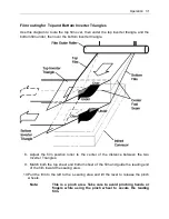
11. Pull the two leading edges of the film into the film drive chain so that the pinch
wheel and drive chain will grab the film when the lever is lowered and begin
pulling the film when activated. Lower the lever to engage the pinch wheels.
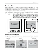
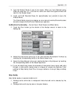
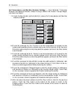
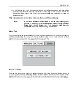
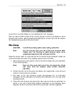
12. Tap the Feed button on the touch screen to jog the film under control. Do not
press and hold the button or film will begin to run and seal continuously. The film
will feed into the seal area. Touch the Seal button on the touch screen to cut the
film.
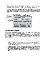
Setup for Scrap Winding
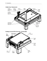
As you run the L-Sealer, excess film will be cut off and exit the front of the chain drive
near the discharge end. To avoid waste film bunching up and creating an obstruction,
the scrap film is routed by rollers to the scrap take-up spool in the base of the L-sealer.
Use the following instructions and illustration at the top of the next page to guide the
scrap film line around the rollers, under the anti-slack tensioner and on to the scrap
take-up spool.
1. As scrap begins to be generated, guide the scrap film around the roller and guide
at the exit end of the L-sealer.
2. Continue to guide the scrap film around the rollers at the front, and under the
machine as shown. Most of the rollers are concealed beneath a guard bracket,
and others are under the machine, but all are accessible and you will be able to
route the scrap film around them.
3. Continue routing the scrap film line around the final roller, under the anti-slack
tensioner, as shown, and onto the scrap take-up spool. Begin winding the scrap
one complete revolution around the center hub of the scrap take-up spool, so the
cling of the film will keep the film on the spool as the drive motor rotates the
spool.
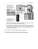
Tap Feed button to
jog film forward
under control.
Touch seal button
to create a seal and
cut the film.
Summary of Contents for Value VSA2530TK-V1
Page 1: ...VSA Value Series Auto L Sealers User Guide VSA2530TK V1 ...
Page 2: ......
Page 4: ......
Page 73: ...Appendix A Electrical Schematic 73 VSA2530 TKV1 Sheet 2 of 5 ...
Page 74: ...74 Appendix A Electrical Schematic VSA2530 TKV1 Sheet 3 of 5 ...
Page 75: ...Appendix A Electrical Schematic 75 VSA2530 TKV1 Sheet 4 of 5 ...
Page 76: ...76 Appendix A Electrical Schematic VSA2530 TKV1 Sheet 5 of 5 ...
Page 78: ...78 Appendix A Electrical Schematic VSA2530 TKV2 Sheet 2 of 6 ...
Page 79: ...Appendix A Electrical Schematic 79 VSA2530 TKV2 Sheet 3 of 6 ...
Page 80: ...80 Appendix A Electrical Schematic VSA2530 TKV2 Sheet 4 of 6 ...
Page 81: ...Appendix A Electrical Schematic 81 VSA2530 TKV2 Sheet 5 of 6 ...
Page 82: ...82 Appendix A Electrical Schematic VSA2530 TKV2 Sheet 6 of 6 ...
Page 83: ...Appendix B Air Diagram Pneumatic Schematic 83 Appendix B Air Diagram Pneumatic Schematic ...
Page 88: ......

