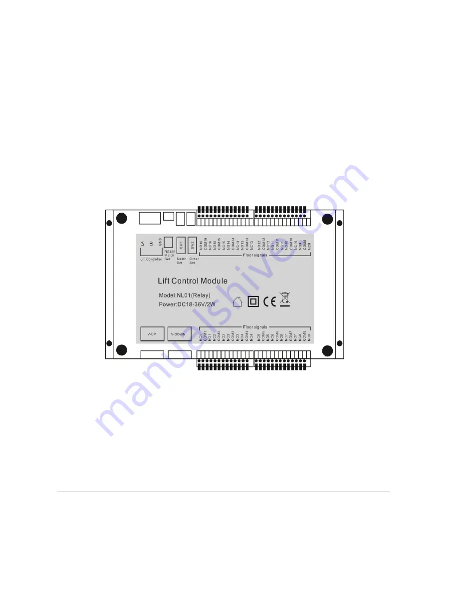
EALINK NL01 User Manual Download Page 1


Lift Control Module 

                                              User Manual 


·

Thank you for purchasing our products.


·

Please carefully read this User's Guide(in particular, precautions for safety) before using a product and follow instructions 

to use a product exactly. 

·

The products are subject to change without prior notice.


Summary of Contents for NL01

Page 1: ...k you for purchasing our products Please carefully read this User s Guide in particular precautions for safety before using a product and follow instructions to use a product exactly The products are subject to change without prior notice ...

Page 2: ...ex 1 Warning 1 2 The outlook and ports of the product 1 3 Features 错误 未定义书签 4 Package content 2 5 System wiring 2 6 Installation 3 1 Surface mounted 3 2 Guide rail mounted 3 7 Specification 4 Version V1 0 ...

Page 3: ...product near a heat or humid place 4 It s forbidden for any unprofessional people to change the coding switch or the connection wires 2 The outlook and ports of the product 1 Vertical upward bus port 1 4 Lift control port for 9th to 16th floor 2 Vertical downward bus port 2 5 Coding switch 3 Lift control port for 1st to 8th floor 6 Reserve RS485 Port ...

Page 4: ...or maintenance Relay output support all kinds of lift control system Signal isolation function can make the system work more stable 4 Package contents Lift control module User manual Desiccant 4 M4 30 fixing screws 4 Expansion bolt 5 System wiring 1 The connection way is same as vertical distributor it can be connected into vertical bus as below diagram see below bold cable The cable is standard C...

Page 5: ...lights would be on at standby state When they are flickering every 1 second it means the communication on vertical bus is abnormal When they are flickering 3 times every second it indicates that the voltage on the vertical bus is too low It can check the power load status when install the system the green lights do not flicker at standby state and will flicker quickly when there s communication Wh...

Page 6: ...7 Specifications NO Item Specification 1 Operation voltage DC18V 36V 2 Operation Currency 200mA max 30mA standby 3 Operation temperature 30 to 50 4 Operation humid 0 95 5 Lift control signal 16 channels relay output NO NC optional no screw needed 6 Extended lift control module quantity 4 Maximum support 64 floors 7 Communication mode CAN bus 8 Communication signal isolation mode Optoelectronic iso...

Reviews: