PCI 703 User Manual
Eagle Technology - Data Acquisition
Eagle Technology © Copyright 2001-2004 – www.eagledaq.com
23
Analog Input
The PCI703 has got a very unique A/D subsystem and is fully configurable. Configuration
includes dynamic range, gain, reference and differential or single ended. Each of these
settings can be applied to an individual channel while scanning.
Please not that although the PCI703 and PCI703S is similar in operation and uses the same
functions, not all parameters apply to the PCI703S. This is because the PCI703S only
supports bipolar-differential mode. The frequency is also implemented differently. Where the
frequency is the timer tic for the ADC on the PCI703, it is the total frequency on the PCI703S.
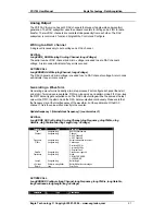
Reading a single voltage from a channel
To read a single ADC channel you need to know the voltage range and gain.
API-CALL
Long EDRE_ADSingle (ulng Sn, ulng Channel, ulng Gain, ulng Range, plong uVoltage)
Parameter
Type
Description
Sn
Unsigned long
Board’s serial number
Channel
Unsigned long
ADC Channel
Gain
Unsigned long
Gain code. See appendix for details
Range
Unsigned long
Range code. See appendix for details
uVoltage
Pointer to a long
Voltage read from channel
Return
Long
Error Code
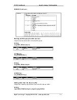
ACTIVEX CALL
Long EDREADX.SingleRead (long Channel)
Parameter
Type
Description
Channel
Long
ADC Channel
Return
Long
Voltage returned from channel.
Make sure to set the
Gain
and
Range
properties of the ADC ActiveX control. This will in turn
set the range and gain when reading the ADC channel.
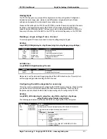
Configuring the ADC subsystem for scanning
This is the most complicated part of configuring the PCI703 for auto scanning. Make sure that
you use the correct format when applying the channel list configuration. There are many
loopholes and care should be taken when implementing code to configure the PCI703.
API-CALL
Long EDRE_ADConfig (ulng Sn, pulng Freq, ulng ClkSrc, ulng Burst, ulng Range,
pulng ChanList, pulng GainList, ulng ListSize)
The following parameters must be specified when configuring the ADC sub-system.
Parameter
Type
Description
Sn
Unsigned long
Board’s serial number.
Freq
Pointer to an
unsigned long
Sampling frequency. The actual sampling frequency will be returned with this parameter.
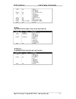
ClkSrc
Unsigned long
This parameter is used to configure the clocking system of the ADC.
Format
Offset (bits)
Description
0
Clock Source (C0-C7)
0: Undefined
1: Internal
2: External – PIN PFI2/CONVERT
8
Trigger Source (T0-T3)
0: Internal
1: Reference – DAC CHAN 1 (NOT SUPPORTED BY PCI 703S)
2: External – PIN TRIG1


