PCI 703 User Manual
Eagle Technology - Data Acquisition
Eagle Technology © Copyright 2001-2004 – www.eagledaq.com
14
Signal Definitions
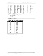
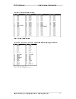
This sections deal with all the signals abbreviations.
Signal
Description
ACH0-63
Analog inputs
AIGND
Analog input ground
AOGND
Analog output ground
AISENSE
Analog input sensing
DAC0-1
Analog outputs
DIO0-7
Digital inputs/outputs
PFI0-9
Programmable multi function digital inputs/outputs
TRIG1
Digital trigger pin
FREQ_OUT
Frequency generator
SCANCLK
A/D external convert
GPCTR0-1
Counter Outputs
CPCTR0-1
Counter Inputs
+5V
Power output
DGND
Digital ground
Table 3-2 Signal definitions
Pin Descriptions
Analog Input (ACH0-63)
This is the analog input-channels. Depending on the version there are either 16/64 single
ended input channels or 8/32 differential input channels.
Analog Input Sensing (AISENSE)
This input is used as a reference analog input ground. This is normally used where the
measurement point is very far from the PCI703 connector.
Analog Input Ground (AIGND)
This is the analog reference used by single ended analog inputs.
Analog Output Ground (AOGND)
This is the analog reference used by analog outputs.
Analog Outputs (DAC0 -1)
The A version of the PCI703 has two analog outputs, DAC0 and DAC1.
Digital Input/Outputs (DIO0-7)
The DIO0-7 pins are the pins for the digital I/O system.
Multi Function Digital Input/Outputs (PIO0 -7)
These pins are digital I/O, but can also be used for some other functions. Th ey represent the
same function as the digital I/O pins.
TRIG1
This pin is used for digital triggering.
Frequency Output (FREQ_OUT)
This is the output pin of the frequency generator system.
ADC Scan Clock (SCANCLK)
This input is used to externally clock the ADC system.


