Dynamatic DCD-132 Instruction Manual Download Page 21

21 


Belt Modulus Factors (Mf) 

Table 3-4 

Belt Type 

Modulus 

Factor 

Belt Type 

Modulus 

Factor 

0.500 

5.938 

0.813 

3V 

0.375 

2.500 

5V 

0.750 

5.000 

8V 

1.563 


Pf = Position factor, a factor used to correct overhung load 

capacity when the center of belt pull is not on the 

center of the shaft keyway extension. Location 

"L" is on the center of keyway. See Table 3-4 

and Figure 3-1. 

Mf  = Belt Modulus Factor from Table 3-5. 


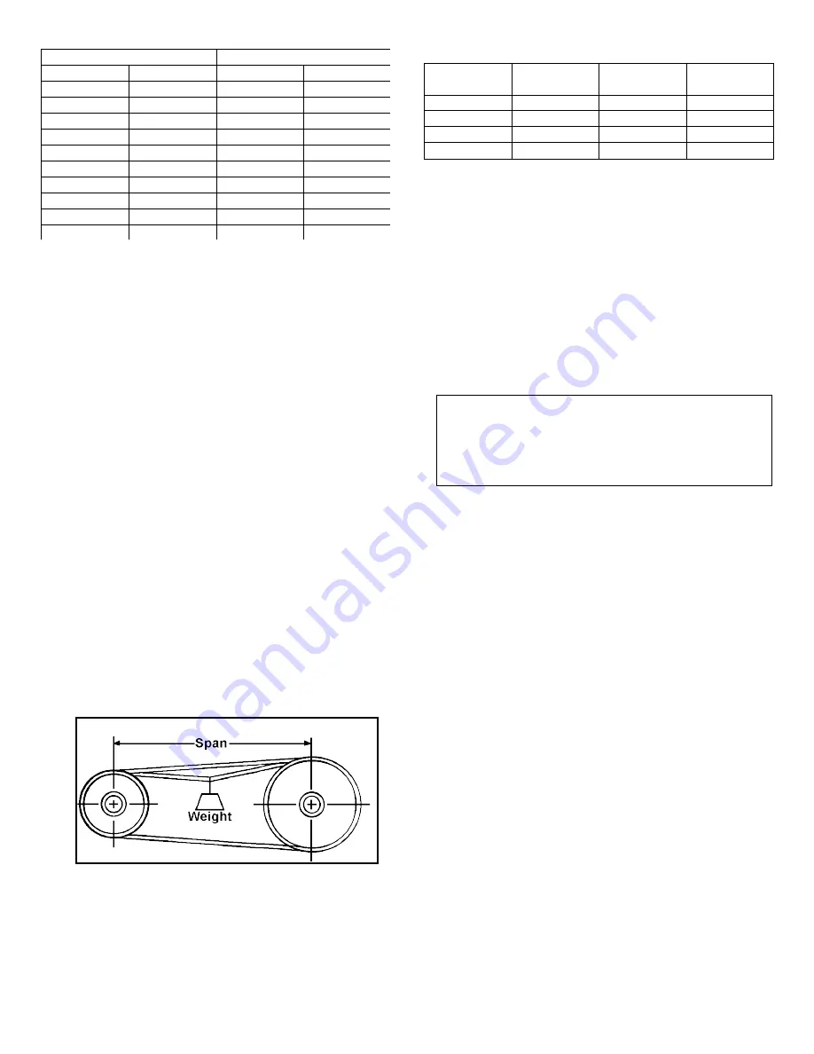
2.  Apply deflection pressure by hanging a weight on 

each belt at the midpoint of the span as shown in 

Figure 3-7. Pressure can also be applied using a 

small spring scale. When properly adjusted, each belt 

should deflect "1/64" for each inch of span. 

3.  If belts slip after tension has been properly adjusted, 

sheaves or belts have been improperly sized. 

4.  With new belts, tensions should be checked and 

adjusted after each 24 hours of operation until belts 

are broken in. 


Final Mounting 

After completing the initial mounting procedures and 

necessary alignment, secure the unit as follows: 

1.  Make sure unit is level and its feet are still in contact 

with the mounting pads. If several  thin shims were 

installed during alignment, consider replacing them 

with thicker shims. A few thick shims are preferred to 

many thin ones. 

2.  Tighten mounting bolts or nuts to secure unit to base. 

Recheck alignment and, if necessary, correct it. 

Tightening bolts may pull unit down, especially when 

many shims are used. 


Precision Tension Check 

Figure 3-6 


3.  For directly coupled units, dowel all interconnected 

units to base to ensure that shaft alignment will be 

maintained. For belt coupled units, recheck belt 

tension arid correct it if necessary. Tightening bolts or 

nuts may have moved unit, causing over- tensioning, 

even though tension was proper before bolts were 

tightened. 

Lubrication 

Bearings are grease lubricated and require no special 

attention unless stored for over one year. Consult the 

sections on "Storage" and/or "Maintenance" for greasing 

instructions. 


Shaft and Belt Guards 

Before applying power and starting the unit, install guards 

over all rotating shafts, couplings, belts and chain 

devices. Refer to OSHA rules and regulation, paragraph 

1910.219 for requirements covering guards on 

mechanical power transmission apparatus. Be sure 

machine is safe to operate and all safety devices have 

been installed, checked out and made operable. 

CAUTION

: When designing belt and shaft guards, 

remember that bearings must be lubricated 

periodically. Grease fittings should be accessible 

through openings in guards and signs should indicate 

the exact location of each grease inlet and outlet. 


Electrical Wiring 

All wiring to the drive, including any accessories, must 

conform to the National Electrical Code  and all other 

applicable state and local codes. Motor leads and 

transformer winding leads are terminated in a conduit box 

mounted on the side of the motor. Leads for the clutch and 

tachometer generator are terminated in a conduit box 

mounted on the clutch housing.  Accessories may also be 

wired to the same conduit box or may be terminated in 

another conduit box attached to the accessory. 

Connections from the conduit boxes to the controller are 

made by connecting each lead or  terminal to the 

appropriate lead or terminal in the controller as shown on 

the connection diagram furnished with the controller. 

Figure 3-8 shows typical connections for a standard drive 

without any modifications or accessories. Section 8 of this 

manual includes typical connection diagrams for common 

accessories. For specially modified drives, refer to the 

instructions furnished for the modification or added 

accessory and to the instructions and diagrams furnished 

with the controller. Tachometer generator leads and 

speed signal  reference  leads should not be run in the 

same conduit with motor power leads. 


Transformer Winding (Applies to Models DCD-132 

through DCD-225 ONLY) 

The motor furnished with the drive DO NOT INCLUDE a 

single phase, 115-volt, center tapped transformer winding 

that can be used as a power source for the external 

controller. The controllers requires a separate power 

source. 

Span 

“Y” Dimension 

Inches 

mm 

Inches 

mm 

60 

1525 

2.50 

63 

80 

2030 

2.75 

70 

100 

2540 

3.00 

76 

120 

3050 

4.00 

101 

140 

3560 

5.25 

133 

160 

4060 

6.50 

165 

180 

4570 

7.75 

200 

200 

5080 

9.00 

230 

220 

5590 

10.50 

270 

240 

6100 

12.00 

305 


Summary of Contents for DCD-132

Page 1: ...ROUGH 160 EDDY CURRENT DRIVES INSTRUCTION MANUAL Revised 2021 DRIVE SOURCE INTERNATIONAL INC 7900 Durand Avenue bldg 3 Sturtevant WI USA 53177 Toll Free 800 548 2169 Phone 262 554 7977 Fax 262 554 7041 Email sales dynamatic com ...

Page 2: ... Factory recommended test procedures included in the instruction manual should be followed Always disconnect electrical power before working on the unit REFER TO OSHA RULES AND REGULAT IONS PARAGRAPH 1910 219 FOR GUARDS ON MECHANICAL POWER TRANSMISSION APPARAT US Note Since Improvements are continually being made to available equipment the enclosed data is subject to change without notice All draw...

Page 3: ...tronic failure Be sure to consider this factor in selecting gear ratios and safety devices Always Wear Safety Glasses Safety glasses should be worn by all personnel involved in installing or maintaining the equipment This applies equally to all electrical and mechanical workers Other safety clothing should be selected as appropriate to the task and work environment Copyright Drive Source Internati...

Page 4: ...eparation 17 Unit Preparation 17 Sizing Sheaves and Sprockets Overhung Load 18 Installing Sheaves Sprocket or Couplings 18 Initial Mounting 19 Alignment 19 Direct Coupled Shafts 19 Parallel Connected Shafts 20 Belt Tension 20 Final Mounting 21 Lubrication 21 Shaft and Belt Guards 21 Electrical Wiring 21 Transformer Winding Applies to Models DCD 132 through DCD 225 ONLY 21 AC Motor Leads 22 Clutch ...

Page 5: ...hooting 28 Dis Assembly Instructions 30 Assembly Instructions 31 Drive Feet Mounting Procedure 33 Section 7 34 Service Renewal Parts 34 Field Service 34 Repair Service 34 Return Instructions 34 Repair Instructions 34 Renewal Parts 34 ...

Page 6: ...ment Check Figure 3 2 20 Angular Alignment Check Figure 3 3 20 Parallel Shaft Alignment Figure 3 4 21 Perpendicular Shaft Alignment Figure 3 5 21 Precision Tension Check Figure 3 6 22 Belt Modulus Factors Mf Table 3 4 22 Typical Wiring Connections Figure 3 7 23 Tach Generator Leads Table 3 5 23 Maintenance Check List Table 6 1 27 Typical Assembly Drawing of DCD Drive Figure 6 1 28 Recommended Grea...

Page 7: ...ructions and procedures Heed any hazard labels on the equipment and be sure to instruct others in their meaning and importance The various types of labels used to alert personnel of hazards and their degree of hazard potential are as follows DANGER Used to call attention to an immediate hazard where failure to follow instructions could be fatal WARNING Identifies hazards having possibilities for i...

Page 8: ... warranty failure occurs contact your local DSI Dynamatic sales office or the factory s Service Department directly for instructions on how to obtain the required repair All repair arrangements must be approved by DSI Dynamatic in advance of returning any products to the factory Note that freight charges both ways are your responsibility For additional information refer to Section 7 Service and Re...

Page 9: ...e shaft to stop in a different position each time The bearing chambers of grease lubricated machines are packed with grease at assembly and should not require additional grease unless unusually severe environmental conditions exist Refer to Section 6 for grease specifications and procedure to follow if periodic greasing is necessary Consult the Service Department at the factory whenever a question...

Page 10: ...dard motors by matching the torque ratings of the motors to the clutch ratings taking into consideration starting torque overload torque speed range and thermal limits The resulting motor and clutch combinations comprise the adjustable speed drive product line Standard horsepower and speed range selections specifications application engineering data and outline drawings can be found elsewhere in t...

Page 11: ...e increases Similarly torque is increased by increasing field coil current This torque versus slip with various current relationships is shown in Figure 2 3 Because some slip must occur to produce the required torque no torque is produced at zero rpm For this reason maximum output speed is always less than motor speed Since the eddy current clutch is a torque transmitter it has no inherent speed s...

Page 12: ...ameplate of each unit is stamped to show the minimum operating speed at full load The minimum speed can be reduced when the load is also reduced Tables found elsewhere in this section list the horsepower capacities and speed ranges of standard drives For other ratings consult the factory The formula shown below is used to calculate the minimum continuous operating speed for a given load torque and...

Page 13: ...he two model types covered by this manual The two model types differ in speed range and torque capability as indicated by the rating tables listed on the following pages Both model types are equivalent in the following respects 1 Weights and dimensions when motors and output bearings are equivalent 2 Clutch coil data current and resistance for 45V coil 3 Overhung load capacity when furnished with ...

Page 14: ...FC Motor Frame Size 3 1630 0 DCD 132030 4141 145TC 5 1500 0 DCD 132050 4141 145TC 5 3300 0 DCD 132050 4121 182TC 7 5 3300 50 DCD 132075 4121 184TC 7 5 1660 350 1680 50 DCD 132075 4141 DCD 160075 4141 213TC 213TC 10 3250 0 1580 0 DCD 132100 4121 DCD 160100 4141 215TC 215TC 15 3300 0 1550 340 DCD 160150 4121 DCD 160150 4141 254TC 254TC 20 3250 0 1615 145 DCD 160200 4121 DCD 160200 4141 256TC 256TC 2...

Page 15: ... on right or left side Totally enclosed covers are available for several models Alternate flanges are available for basic and freestanding models see page 54 Weight is approximate and includes motor Dimension includes flange see page 54 DIMENSIONS ARE IN INCHES Model Hp Frame AC LE AA 2E 2F KK 3 182TC 8 8 13 65 75 DCD 132 5 7 5 184TC 213TC 8 8 10 25 14 50 15 00 75 1 00 10 215TC 10 25 16 25 1 00 7 ...

Page 16: ...16 Alternate Flange Outline Dimensions Model C LA LF M N P T NW SS DCD 132 4 84 74 7 4 6 10 8 46 9 84 16 2 75 6 DCD 160 7 87 63 8 74 10 43 9 06 14 0 16 3 375 6 DIMENSIONS ARE IN INCHES ...

Page 17: ...vertical model that is specifically designed for vertical mounting and operation Other models must be mounted horizontally unless certified drawings or other documentation furnished for equipment supplied for a specific customer order indicates that the equipment is designed for vertical mounting and operation Operation in ambient above 104ºF 40ºC requires the HP dissipation to be de rated 10 for ...

Page 18: ... load ratings listed in Section 2 are for units with a standard length output shaft and either standard output ball bearing or optional standard output spherical roller bearing as indicated in the tables Units with an external brake have a longer shaft Separate overhung load rating tables are provided for units with a brake For non standard models contact DSI Dynamatic to obtain the overhung load ...

Page 19: ...ignment Offset Alignment Check Figure 3 2 Note Dial indicators used for alignment must be non magnetic due to possible magnetism of the unit s shaft If possible rotate both shafts when required in procedure If one shaft cannot be turned alignment can still be checked by rotating the other shaft with indicator attached to it 1 Clamp base of indicator to hub of unit s shaft and position its indicato...

Page 20: ...f the horizontal shaft as shown in the front view a line perpendicular to the vertical shaft at the center of its sheave must pass a distance Y below the center of the horizontal shaft Belt Tension Belt and chain drives are tensioned by sliding the unit sideways after loosening the hold down bolts It is very important to establish the proper tension which is one just above the point of slippage Be...

Page 21: ...ting shafts couplings belts and chain devices Refer to OSHA rules and regulation paragraph 1910 219 for requirements covering guards on mechanical power transmission apparatus Be sure machine is safe to operate and all safety devices have been installed checked out and made operable CAUTION When designing belt and shaft guards remember that bearings must be lubricated periodically Grease fittings ...

Page 22: ...tions furnished with the eddy current controller Tachometer Generator Leads The tachometer generator leads are connected to the same terminal block as the clutch and brake leads described above Three tachometer generator leads are brought out to the conduit box in a shielded insulated cable Two of these leads are connected to terminals G1 and G2 according to maximum output speed as shown in Table ...

Page 23: ...ycle requires frequent overloads or frequent motor stops starts or reversals the application should be reviewed and specific limits determined Consult the factory Under normal speed control the controller is constantly regulating clutch coil current to maintain set speed Motor current and clutch coil excitation will vary in proportion to the amount of regulation required This is normal do not expe...

Page 24: ...ation through the grille on clutch housing If the direction is not correct turn AC power OFF lock out the disconnect switch and reverse any two of the three incoming power leads then repeat the test to ensure proper rotation 5 Start the AC motor and observe its operation Listen for any abnormal noise or vibration Using a clamp on ammeter check motor current All three phases should be balanced If a...

Page 25: ... Erratic speed control or abnormal response will usually affect the product being manufactured When the clutch does not seem to control the way it should the problem can be either electrical or mechanical When investigating check for loose belts loose setscrews overloading and other mechanical problems It is not always the fault of the controller Motor current should be monitored it can indicate m...

Page 26: ...ictated by the environment of the unit The more severe dirty or hot the conditions are the more often these tasks must be performed Before doing any work turn AC power OFF and lock out disconnect switch Clean accumulated dust and dirt from the unit and immediate area Pay special attention to air intake areas under end bracket Dirt allowed to accumulate there can easily obstruct airflow or be drawn...

Page 27: ...ed at the factory Recommended amounts of grease for the bearings are listed in Table 6 3 Any equivalent and compatible grease may be used Special greases may be specified at the time of order entry Consult your order papers if a special grease has been specified When lubrication is required use the following procedure to grease the bearings 1 Stop the motor and clutch and allow both to coast to a ...

Page 28: ...rt 1 Lost power or phase blown fuse 2 Wiring loose incorrect grounded or shorted 3 Open or defective switch circuit breaker or motor starter 4 Open or defective overload or safety interlock 5 Defective start stop buttons or control circuit wiring 6 Motor winding grounded shorted or otherwise defective 7 Mechanical defect inside motor or clutch Motor does not run properly noisy erratic imbalanced c...

Page 29: ...nd rotor 7 Bent shaft Unit overheats 1 Overload 2 Operating below minimum speed 3 Air passage blocked 4 Recirculating cooling air or ambient temperature 5 Brake not releasing Bearing overheats 1 Bearing failing 2 Excessive thrust or overhung load 3 Lack of excessive or wrong lubricant 4 Unit misaligned 5 Bent shaft Erratic operation 1 Controller malfunction check controller 2 Cyclic or shock loadi...

Page 30: ...To separate the coil and tach wires cut the waxed string and carefully slide the rubber tube off If the tach is being replaced a string or small wire tied to the old tach wires before removing can be used to assist in pulling in the new wires Note Broken wires tach should be 220 ohms a bad tach will cause the drive to run at full speed when the controller is energized 6 Remove the tach cover plate...

Page 31: ...Mount the front bearing retaining ring onto the shaft Insert the shaft assembly into the output assembly from the front side by pressing on the inner and outer front bearings while supporting the rear bearing 4 Mount the star tolerance ring and tach armature onto the shaft Feed the tach wires through the hole in the output assembly and slide the tach stator plate over the shaft and bolt to the out...

Page 32: ...0HP 95012 02 STD COIL FOR 4 3HP 4 4HP 2 5HP 2 7 5HP 95013 03 HP COIL FOR 4 5HP 2 10HP 95013 04 HP COIL FOR 4 3HP 4 4HP 2 5HP 2 7 5HP 95002 02 95002 01 TORQUE TUBE ROTOR ASSY 4 POLE 95004 01 95004 02 BLADED POLE WHEEL STD 95004 01 95004 02 BLADED POLE WHEEL REDUCED 95002 02 95002 01 TORQUE TUBE ROTOR ASSY 2 POLE 95004 01 95004 02 BLADED POLE WHEEL REDUCED C W AXIAL BLADES 95002 02 95002 01 TORQUE T...

Page 33: ...en bolts 5 Re check alignment and change shims as required 6 Push slotted shims under AC Motor mounting feet and moderately tighten the bolts Note The decision to mount bolt the motor feet should be based on the application dynamics i e vibration support It is not always necessary to mount the motor feet and is specifically motor size related Note When Drives are purchased with a base the base mus...

Page 34: ...m Contact your local Sales Office for the form and return authorization Provide all the information requested on the form and return it with the equipment and your purchase order Those items not manufactured by DSI Dynamatic such as instruments meters and digital counters are repaired by the vendor Returning them to the factory will only delay the repair Contact the Repair Service Department at th...

Page 35: ...DRIVE SOURCE INTERNATIONAL INC 7900 Durand Avenue Bldg 3 Sturtevant WI USA 53177 Toll Free 800 548 2169 Phone 262 554 7977 Fax 262 554 7041 Email sales dynamatic com IM 160000 2019 ...

Reviews: