


11
Typical Dynamatic® Model DCD
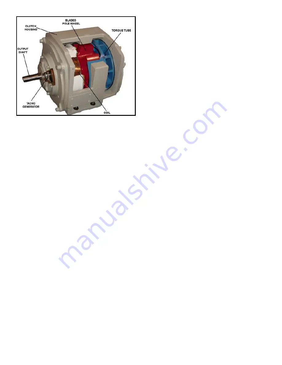
Figure 2-2
Adjustable Speed Drive - Cutaway View
Description of Operation
The eddy-current principle is utilized to transmit power
from the AC induction motor to the load. The clutch input
and output members have no physical contact between
each other, except for the center support bearing. The
clutch couples the motor to the load through a magnetic
field. The motor runs at full speed; it is not stopped or
started each time the load is stopped and started. This
prolongs motor and starter life and it permits the motor to
be started under no-load conditions. The only parts
subject to wear during normal operation are the bearings.
The two major parts of the eddy-current clutch are the
drum assembly and the output rotor and shaft assembly
(see Figure 2-2). The AC motor rotates the drum at a
constant speed, while the rotor and shaft assembly
remains stationary until voltage is applied to the field coil.
With no load attached to the output shaft, bearing friction
and grease in the center support bearing, and windage
between the drum and rotor assembly may produce some
minimal torque and could cause the output shaft to rotate.
The driven load is usually sufficient to hold the output
shaft stationary.
Energizing the field coil produces magnetic flux. This flux
crosses the air gap from the rotor assembly poles to the
drum assembly, passes along the drum assembly axially
and returns across the air gap back to the rotor assembly
poles. This magnetic flux path is disrupted when the drum
is rotating relative to the rotor assembly.
As a result, eddy-currents are generated in the inner
surface of the drum. These eddy-currents produce a
series of magnetic poles on the drum surface that interact
with the electromagnetic poles of the rotor assembly to
produce torque. It is this torque that causes the rotor
assembly and output shaft to rotate with the motor.
To generate eddy-currents and produce torque, there
must be a relative speed difference between the clutch
drum and rotor assembly. This speed difference is called
“slip”. With zero slip, there are no eddy-currents
generated and no torque produced. As slip increases,
torque increases. Similarly, torque is increased by
increasing field coil current. This torque versus slip, with
various current relationships, is shown in Figure 2-3.
Because some slip must occur to produce the required
torque, no torque is produced at zero rpm. For this reason,
maximum output speed is always less than motor speed.
Since the eddy-current clutch is a torque transmitter, it has
no inherent speed sense. Without external control, output
speed depends on load. This feature is frequently used to
advantage in helper drives, tensioning drives and winder
applications where torque is the prime requirement. When
speed control is needed, a tachometer generator provides
velocity feedback to an electronic controller. The controller
varies field coil current to match torque output with load
demand to hold desired preset speed.
A tachometer generator is included in each clutch for
velocity feedback. The rotor, a permanent magnet with
alternating poles around its outer diameter, is locked to
the output shaft near the output end of the clutch. The
rotor is positioned inside a laminated field winding. An AC
voltage proportional to speed is generated in the field
winding.
Construction
The input drum of the magnetic clutch is mounted directly
on the motor shaft and it is supported by the motor
bearings. The output rotor and shaft assembly is
supported by a bearing on the end of the motor, or input
shaft, and a bearing in the output end bracket. They are
referred to as the center support bearing and output
bearing, respectively.
In the cutaway view in Figure 2-2, note that the clutch
excitation coil is mounted on a stationary ring that extends
into a hollow space in the output member. This allows the
coil leads to be wired directly to the conduit box without
requiring slip rings and brushes.
Cooling
Eddy-currents in the inner surface of the drum produce
heat. This heat is proportional to slip and is sometimes
referred to as "slip heat." The greater the load and the
slower the speed, the greater the heat generated.
Conversely, very little heat is produced at full speed.
Air is used to cool the clutch. The input drum acts as a
fan, drawing air in through the output end bracket and
across both sides of the drum. Air is discharged through
openings on both sides of the housing. Since the drum is
driven by the motor at a constant speed, maximum
cooling is achieved.