Dynacord PM 502 User Manual Download Page 25

Notice!
Effect of MIC PROCESSING
The AUX-Bus signal is only affected by MUTE, so COMPRESSOR or TALK OVER have no effect
on the AUX-Bus signal.

COMPRESSOR
Engage the COMPRESSOR switch to activate the integrated compressor. The compressor
reduces the dynamic range of audio signals. Once the signal exceeds a certain threshold, the
signal gets compressed, i.e. major input level changes result in minor output level changes.
Narrowing the dynamic range often allows for easier recording or mixing the audio signal.
TALK OVER
Engage the TALK OVER switch to activate the integrated ducking facility. The ducking facility
reduces the level of the signals at the STEREO inputs whenever a signal is present at the MIC/
LINE inputs. If there is no MIC/LINE signal present the STEREO signal automatically returns to
its preset level.
MUTE
Engage the MUTE switch to mute all MIC/LINE input signals.
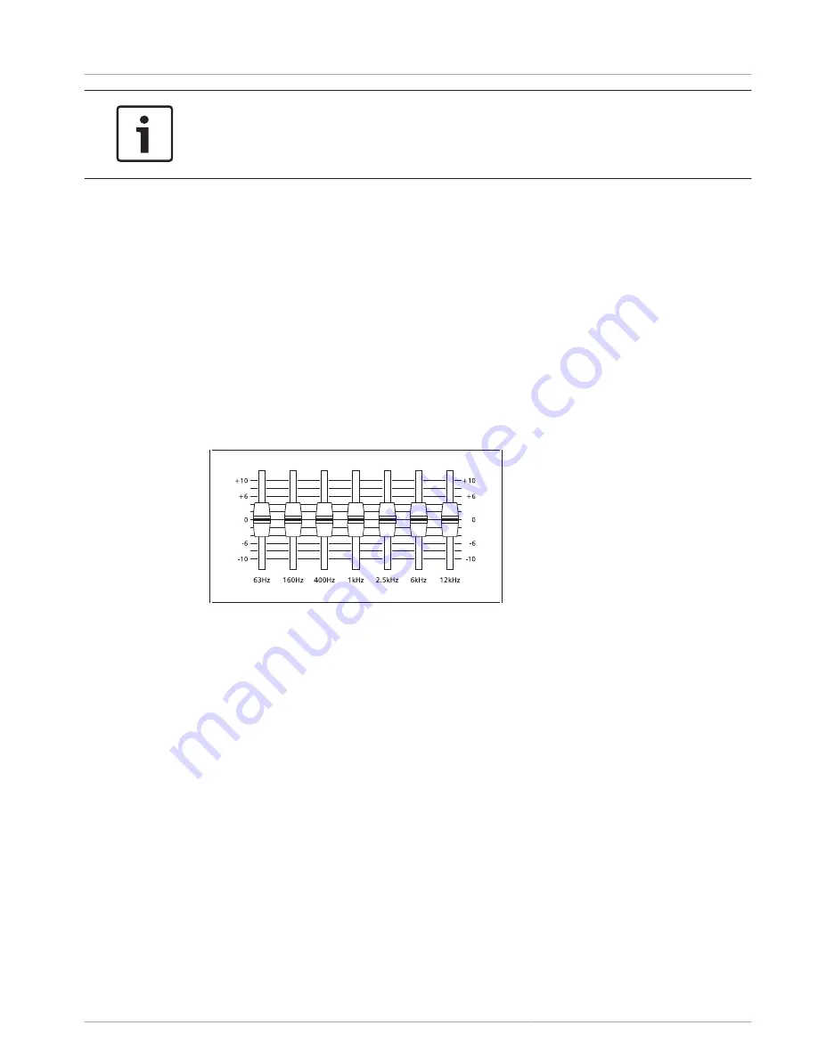
Equalizer

The PM 502 employs a 7-band stereo graphic equalizer (GEQ). Seven frequency bands offering
10 dB gain/reduction and a quality of Q = 1.5 allow the shaping of the overall sound to meet
your personal preferences or to optimally match it to the acoustic conditions of different
locations.
Independent graphic equalizers for MASTER A, MASTER B or AUX (each adjustable via
hardware controls or the rotary encoder) are available in the menu, please refer to section
Menu, page 26.
GEQ setting instructions
The frequency ranges as well as the characteristics of the EQ faders are very practice-
oriented. If you want to have a clear and highly intelligible sound, which, as a side effect,
provides the cymbals with a more crisp sound, you should raise the levels of the 12 kHz or 6
kHz band a bit. If the mids are nasa you should attenuate the mid range (400 Hz to 2.5 kHz) by
a few decibels. To provide the kick drum with more punch you have to boost the low
frequency range, using the 63 Hz or the 160 Hz controls. In case the overall sound is undefined
with too much bass, lowering the levels of these two frequency bands will solve the problem.
However, especially with equalization you should be aware of the fact that in most cases fewer
adjustments provide better results. Thus, your first choice should be to establish the mix using
only the input channel controls and see if you get a satisfactory result.


7.7

PM 502

Operation | en

25


Bosch Sicherheitssysteme GmbH

User manual

15-May-14 | 02 | F01U297804

Summary of Contents for PM 502

Page 1: ...PM 502 en User manual...

Page 2: ......

Page 3: ...Phantom power 16 6 2 100 V Direct Drive 16 6 3 Amplifier routing 16 6 4 Speaker processing LPN 17 6 5 AUX mode 17 6 6 Locking 18 6 7 Microphone processing TALK OVER 19 7 Operation 20 7 1 Mono input 2...

Page 4: ...not fit your mains socket please contact your electrician 10 Ensure that it is not possible to stand on the mains cable Take precautions to ensure the mains cable cannot become crushed particularly ne...

Page 5: ...ust be used during any work for which the opened device is connected to and operated with mains voltage 3 The device must be free of any voltage before performing any alterations with upgrade sets swi...

Page 6: ...r environmentally compatible recycling in accordance with the European Waste Electrical and Electronic Equipment Directive To dispose of old electrical or electronic devices you should use the return...

Page 7: ...ns in this document and the safety notes starting on page 4 before you plug your PM 502 into a power outlet Shipping contents and warranty Quantity Component 1 PM 502 1 Power cord 1 User manual 1 Impo...

Page 8: ...System overview Front view Rear view 3 8 en System overview PM 502 15 May 14 02 F01U297804 User manual Bosch Sicherheitssysteme GmbH...

Page 9: ...ore using the PM 502 Do not remove any knobs from the front panel the foil can be easily removed without having to detach the knobs on the control surface Before connecting to the mains supply please...

Page 10: ...s can also be established through monaural or stereo jacks assigned according to the the illustrations in section Pin assignments page 43 If the device that you want to connect has a balanced output s...

Page 11: ...of connection is less sensitive to the introduction of external noise or HF interference If you want to connect a monaural sound source to a stereo input channel use the L MONO input The signal is rou...

Page 12: ...speakers can be connected via speakON or Euroblock connectors High Z speakers shall be connected via the Euroblock connectors only please refer to the following sections speakON The PM 502 is equippe...

Page 13: ...ion of low impedance speakers Euroblock connector in high Z mode When the Direct Drive mode is activated use pin of CH 1 and pin of CH 2 to connect the 100 V loudspeaker line see following illustratio...

Page 14: ...MASTER B L R The MASTER B L R outputs the L R master audio signal is present that can be used for additional monitoring side fill and additional zone applications or for the connection of a delay line...

Page 15: ...e to the USB port on the front panel to use the integrated audio player of the PM 502 The external memory is scanned automatically for suitable audio tracks MP3 or WAV If audio tracks are detected the...

Page 16: ...aker lines Next to 100 V loudspeaker lines it is possible to drive 70 V loudspeaker lines In this case the limiter of the channel selected for Amp Routing e g MASTER A has to be set to 3 dBu in the OU...

Page 17: ...setting The following table describes the available LPN filter settings Setting SPEAKER PROCESSING indicator Description HIGH ON In setting HIGH the LPN filter is activated this setting is recommended...

Page 18: ...pped post MASTER A volume control and therefore affected by the MASTER A control s setting Table 6 3 AUX modes Locking The PM 502 allows locking certain features or parameter settings in the menu A fo...

Page 19: ...STEREO signal automatically returns to its preset level Please refer to section Menu page 26 how to edit the TALK OVER settings The following diagrams illustrate the available presets The parameters o...

Page 20: ...he left lowers attenuates the signal of that specific frequency band Before you begin to alter the sound all EQ controls should be set to their neutral position i e their marker points straight up loc...

Page 21: ...wn Keeping an eye on the indicator during a performance is also a good idea because some changes in the bands dynamics or even a change in keyboard settings can easily lead to channel clipping resulti...

Page 22: ...post VOLUME control so that the volume setting also influences the amount of the signal that is fed to the FX unit Using the FX controls lets you easily assign an effect for groups of musical instrum...

Page 23: ...PK indicator This indicates to the user that the internal FX unit is on the verge of clipping e g at a level of 6 dB below the risk of overdrive To achieve an adequate signal to noise ratio please adj...

Page 24: ...sk of the degradation of your speaker output In that case the volume level has to be reduced The limiter threshold can be edited in the OUTPUT SETTINGS menu please refer to section Menu page 26 Below...

Page 25: ...preferences or to optimally match it to the acoustic conditions of different locations Independent graphic equalizers for MASTER A MASTER B or AUX each adjustable via hardware controls or the rotary e...

Page 26: ...e equalizer setting of the channel is not set to flat LIM The threshold of the output limiter has been edited Speaker icon Indicates the Amp Routing If a Dual Amp Routing is selected speakers for outp...

Page 27: ...80 Hz or 150 Hz are attenuated COMPRESSOR PRESET Soft Hard COMPRESSOR THRESHOLD The range depends on the selected compressor preset COMPRESSOR TYPE 2 1 Ratio 4 1 Ratio Limiter Uplift Soft COMPRESSOR A...

Page 28: ...signal is not changed and outputted in stereo When Mono is selected the MASTER A L R signal is summed and outputted in mono at MASTER A L and also MASTER A R MASTER B Pre Post Mono Stereo When MASTER...

Page 29: ...allation location Screensaver Off 60 Min default Off Personalize After the time set here the screensaver is activated You can personalize the device name shown in the screensaver screen DEVICE SETUP 2...

Page 30: ...e of degradation in the output sound In that case the MASTER or AUX level has to be reduced The LIMIT LED also lights up if the output level is reduced because of high amplifier temperature or too hig...

Page 31: ...Headphone page 15 Caution Make sure to set the PHONES VOLUME control to its minimum position before connecting headphones Permanent hearing loss may occur if headphones are used at high volume 7 10 PM...

Page 32: ...Maintenance The PM 502 does not require any maintenance 8 32 en Maintenance PM 502 15 May 14 02 F01U297804 User manual Bosch Sicherheitssysteme GmbH...

Page 33: ...er 20 20000 Hz THD 0 5 one channel loaded into 4 400 W into 8 240 W Max output power Direct Drive mode bridge configuration continuous 1 kHz THD 1 into 12 680 W Max output voltage power amplifier 1 kH...

Page 34: ...dBu Mono line inputs GAIN at min position 30 dBu Stereo line inputs 26 dBu PHONES output 21 dBu MASTER A B AUX outputs 11 dBu Input impedances MIC 2 k CD 10 k All other inputs 15 k Output impedances...

Page 35: ...ctory presets user editable Remote control Footswitch Display 128 x 64 pixels LCD Audio player USB at front panel Switching mode power supply C controlled FAT 32 Supported audio file formats MP3 WAV I...

Page 36: ...ct dimensions Width x Height x Depth 395 x 244 x 241 mm Rack mount 483 x 223 x 310 3 mm 7 HU Net weight 4 9 kg Shipping weight 6 4 kg Table 9 1 Device in rated condition MIC GAIN 15 dB STEREO GAIN LO...

Page 37: ...Dimensions 9 1 PM 502 Technical data en 37 Bosch Sicherheitssysteme GmbH User manual 15 May 14 02 F01U297804...

Page 38: ...NO MASTER B AUX DELAY PRE POST A AUX LIMITER LIMITER LIMITER MASTER A MASTER B L L R R AUX OUT LO CUT LPN LIMITER PROTECT ROUTING CH1 CH2 MUTE AMP PROTECT AMP LIMIT SPEAKER PROC DIRECT DRIVE 20dB LO H...

Page 39: ...r output channel low Z mode Powered speakers and subwoofers are connected to MASTER B or AUX OUT Signal sources are connected via mic line level inputs and USB Additionally an USB stick is connected f...

Page 40: ...akers e g D 8A as side room PA are connected to MASTER B Powered monitor speakers e g AXM 12A are connected to AUX OUT Signal sources are connected via mic line level inputs Additionally an USB stick...

Page 41: ...four TS 100 speakers is connected to MASTER A output set to Mono A PCL power amplifier driving four DL 800 horns is connected to MASTER B set to Mono Signal sources are connected via mic line level i...

Page 42: ...PowerSub 312 driving six TS 100 speakers is connected to MASTER A output A PCL power amplifier driving another 100 V speaker line zone 2 with ceiling speakers is connected to MASTER B set to Mono As s...

Page 43: ...SHIELD COLD HOT Figure 10 2 Balanced assignment of stereo jack Figure 10 3 Pin assignment of XLR microphone input with phantom power Figure 10 4 Pin assignment of speaker output CH 1 2 low Z speakON 1...

Page 44: ......

Page 45: ......

Page 46: ......

Page 47: ......

Page 48: ...Bosch Sicherheitssysteme GmbH Robert Bosch Ring 5 85630 Grasbrunn Germany www dynacord com Bosch Sicherheitssysteme GmbH 2014...

Reviews: