DW-CP04 Quick Start Guide
Live/ Playback/ Admin/ Home views
OVERVIEW
USER INTERFACE
HARDWARE
OVERVIEW
7
8
9
10
11
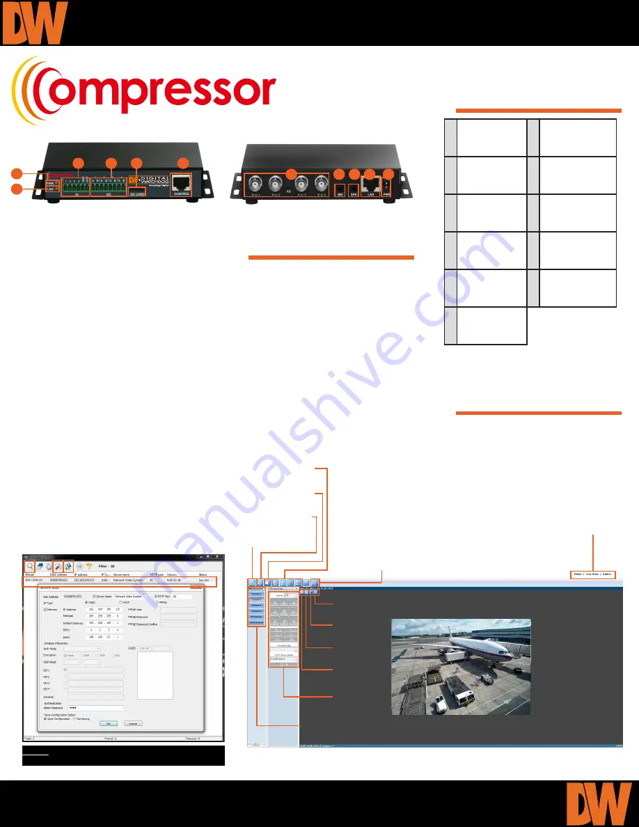
Network LED
Sensor Input Ports
1~4
Alarm Output
Port 1~4
Mirco SDHC Slot for
On-Board Storage
Control Port: RS-
485, RS-232, DI, DO
1 Analog Channel
Input1~4
2 Audio Input Port
3 Audio Output Port
4
Ethernet
Network Cable
5 Power Supply
12VDC, 1A
6 Power LED
CONFIGURING THE COMPRESSOR
1. Mount and connect your analog cameras. Consult the camera’s manual for additional
information.
2. Connect the cameras’ video output to the Compressor’s BNC Input ports.
3. Connect the Compressor to your network using a LAN Cable.
4. When all extrenal devices have been properly connected to the Compressor, connect the power
cable to the back of the encoder.
5. Run the IP Finder software included with the Compressor’s accessory CD on a computer located
in THE SAME network as the Compressor.
6. Press the Search button to detect all supported devices located on the network. Allow up to 1
minute for the system to perform the search.
7. If necessary, press the IP Setup tool to properly configure the Compressor’s IP Address and
network information to match your security settings. (Enter admin’s pasword, ‘root’, at the bottom
of the page and press ‘Set’ to save the changes.)
8. Double-click the Compressor’s name or press the ‘Home’ button to go to the Compressor’s Web
Page for additional setup and remote viewing.
Toll Free: 866.446.3595
Fax: 813.888.9262
www.digital-watchdog.com [email protected]
2 3 4
5
1
DW-CP04 Network Video Encoder
6
7
8
9
10
11
Main Display Area
Export Image
Instant
Recording
Playback
About
Software
Image Display
Options
Show/ Hide
Audio Control
Show/ Hide
PTZ Control
Show/ Hide
Channel Control
Channel Display
Options
NOTE:
Default admin user/ password: root / root
Export Clip
PTZ Virtual
Controller


