A-9
2
1
3
4
5
Appendix
I
A
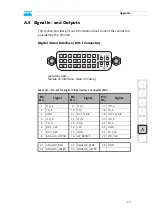
A.5 Signal In- and Outputs
This section provides pin-out information about some of the connectors
provided by the Pronto3.
Digital Video Interface (DVI-I Connector)
Table A-3: Pin-out for Digital Video Interface Connector (DVI)
Pin
No.
Signal
Pin
No.
Signal
Pin
No.
Signal
1
/TX_2
9
/TX_1
17
/TX_0
2
TX_2
10
TX_1
18
TX_0
3
GND
11
DVI_CLK_B
19
/DVI_CLK_B
4
/TX_4
12
/TX_3
20
/TX_5
5
TX_4
13
TX_3
21
TX_5
6
DDC_CLK
14
+5V
22
GND
7
DDC_DAT
15
GND
23
TX_CLK
8
ANALOG_VSYNC
16
HP_DETECT
24
/TX_CLK
C1
ANALOG_RED
C3
ANALOG_BLUE
C5
GND
C2
ANALOG_GREEN
C4
ANALOG_HSYNC
(external view;
female on interface, male on cable)
1
9
17
3
11
19
2
10
18
4
12
20
8
16
24
C1
C2
C4
C3
C5
7
15
23
6
14
22
5
13
21
Summary of Contents for Pronto3
Page 1: ...Pronto3 Hardware Guide Version 1 0 Digital Disk Recorder Pronto3 Hardware Guide ...
Page 2: ......
Page 6: ......
Page 8: ......
Page 36: ...2 18 Pronto3 Hardware Guide ...
Page 38: ...3 2 Pronto3 Hardware Guide ...
Page 68: ...A 16 Pronto3 Hardware Guide ...
Page 72: ...I 4 Pronto3 Hardware Guide VTR 1 1 warranty 1 7 XLR connectors audio 2 13 ...


