Installation and operating instructions
Dart Valley Systems
Tel: +44 (0) 1803 529021
Fax: +44 (0) 1803 559016
www.dartvalley.co.uk
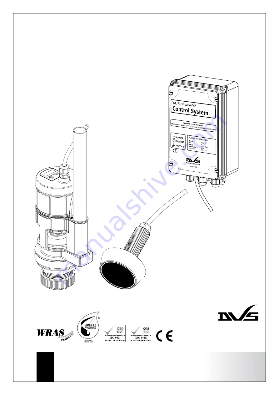
Flushvalve
WC Flushing System V2
with the Fully Automatic Sensor
Model: D103/V2/AUTO
Version. INFL002 v2.1 101111
Page 1: ... operating instructions Dart Valley Systems Tel 44 0 1803 529021 Fax 44 0 1803 559016 www dartvalley co uk Flushvalve WC Flushing System V2 with the Fully Automatic Sensor Model D103 V2 AUTO Version INFL002 v2 1 101111 ...
Page 2: ...reduced physical sensory or mental capabilities or lack of experience and knowledge they must be given adequate supervision or instruction concerning use of the appliance by a person responsible for their safety Children should be supervised to ensure that they do not play with the appliance IMPORTANT Please read these instructions carefully and follow each stage in order Key Right 1 Flush time an...
Page 3: ...ount the control system in a vertical orientation cables exiting bottom in an accessible location no more than 2 metres from the valve and sensor Note The standard cable length to the flushvalve is 2 metres and the sensor is 3 metres Any other lengths are special order Connector plugs The connector plugs can be disconnected from the mating sockets when wiring external equipment double check positi...
Page 4: ...e clamped Check for stray strands If the mains lead becomes damaged the product should not be used Contact DVS for replacement parts A suitable means of disconnection should be provided in accordance with local electrical regulations Safety CAUTION 220 240V a c NEVER open the cover with the supply live Remove old flush handle and its linkage to the syphon Carefully disconnect the existing flush pi...
Page 5: ...IMPORTANT The minimum water level after flush cycle finishes must be 5mm above the Flushvalve window It is very important that the minimum water level does not fall below this level If the level falls below this point the valve operation will be more audible and you also risk damaging the valve The minimum water level is controlled by the flush time on the control system covered later in section 9...
Page 6: ...e enclosure DO NOT interfere with the mains flex DO check all cables and connections DO ask for advice if when necessary This sensor is designed to operate as part of a flushvalve control system which incorporates a flushvalve control unit and power supply This sensor should only be used with the supplied control unit The Auto Flushvalve Sensor is designed to flush the toilet as the user leaves th...
Page 7: ...ify or adjust the length of the sensor cable Key Below 1 Sensor 2 Bezel 3 Backplate 4 Mounting surface 5 Washer 6 Back nut 1 2 3 4 5 6 Safety CAUTION 220 240V a c NEVER open the cover with the supply live DO NOT attempt to make adjustments until the power is isolated IMPORTANT Adjustments will not be implemented unless the supply to the control system has been isolated The Green LED indicates that...
Page 8: ...atic sensor start up routine The function light mounted behind the front face of the sensor indicates the status of the sensor and will flash when it detects a user in the sensor area When the sensor is powered up for the first time it will initiate a 60 second set up procedure Do not move into the sensor area during this time Following initialisation the sensor will enter normal operation The nor...