EN
2012/02
11
3
a
b
c
d
6. Functional Description
Detailleddescriptionsofthefunctionof
eachindividualunitcanbefoundinthe
InstallationandOperatingInstructions
suppliedwiththeappropriateappliance
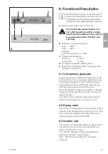
a
Mainpowerswitch:On(I)/Out(0)
Even when the power switch is in
the off (O) position certain compo-
nents are still subject to live current
(e.g. pressure switch, PCB of con-
trol unit).
b
Displayforrelativehumidity:
blue <30%
pink >30%
Display:
optimumrangeca0-30%
c
Pressureleveldisplay
Start-up
60bar
Switch-off
75bar
d
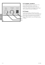
AmalgamSeparatordisplaypanel
e
Displayforoperatingstate,messagesand
operationofthePTS
6.1 Compressor generator
Apressuresensormonitorsthepressureinthe
pressuretankThecompressorgeneratorisau-
tomaticallyswitchedonandoffdependingon
thepressuresettingswhichhavebeensetup
andtheactualpressurewithinthetank
Airatatmosphericpressureisdrawninthrough
thesuctionfilterandtheinletvalveintothecyl-
inderchamber
Thepistoninthecylindercompressestheair
drawninandsuppliesittothedry-airunit
6.2 Drying units
Thishumid,compressedandwarmedairisthen
cooled,driedandfilteredbythedry-airunitThis
thenmaintainsarelativehumidityoftheairin-
sidethepressuretankbelow30%
6.3 Suction unit
Thesuctionunitisstartedeitherbytheremoval
ofsuctionhosefromthehosemanifoldorby
actionofthespittoonvalve
Thevacuumtherebyproducedsuppliesthe
treatmentunitwithsuctionpower
(300-350l/minrateofflowforthelarger
cannula)
e
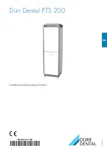
Summary of Contents for PTS 200
Page 1: ...EN 9000 619 14 30 2012 02 Dürr Dental PTS 200 Installation and Operating Instructions ...
Page 2: ......
Page 24: ...EN 24 2012 02 PTS 200 13 Connection media plan 13 1 Set up with VS units ...
Page 25: ...EN 2012 02 25 PTS 200 PC board 13 2 Set up with a display ...
Page 26: ...EN 26 2012 02 PTS 200 13 3 Set up with V units ...
Page 32: ...EN 32 2012 02 400 V 3 part 2 Bleeder valve ...
Page 33: ...EN 2012 02 33 400 V 3 part 3 Display Top Optional Hose manifold con trol switch ...
Page 38: ...EN 38 2012 02 Model type 230V 1 2 aggregates part 3 24 VAC Hose manifold con trol contact ...
Page 47: ......

