Dürkopp Adler 650-16 Operating Instructions Manual Download Page 127

Setup

Operating Instructions 650-16 - 02.0 - 08/2016

125

8.9.7

Connecting the equipotential bonding for the 
additional control

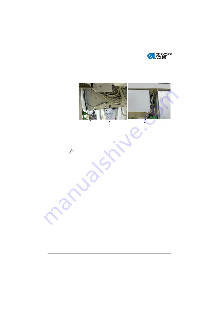
Fig. 82: Connecting the equipotential bonding for the additional control

To connect the equipotential bonding for the additional control:

1.

Plug the protective earth conductor (1) into the flat plug (2) 
on the additional control cabinet.

2.

Lay the cable (2) (300 mm long) to the control cabinet (3) and 
screw it on.

(1) - Protective earth conductor
(2) - Flat plug

(3) - Attachment to control cabinet

Summary of Contents for 650-16

Page 1: ...650 16 Operating Instructions...

Page 2: ...er AG and protected by copyright Any reuse of these contents including extracts is prohibited without the prior written approval of D rkopp Adler AG Copyright D rkopp Adler AG 2016 IMPORTANT READ CARE...

Page 3: ...edle 20 4 4 Threading the needle thread 23 4 5 Winding the hook thread 25 4 6 Replacing the hook thread bobbin 26 4 7 Thread tension 27 4 7 1 Setting the needle thread tension 28 4 7 2 Setting the hoo...

Page 4: ...ual mode MAN 69 6 5 1 Parameters that can be set in MAN mode 70 6 5 2 Sewing process 73 6 6 Automatic mode AUTO 74 6 6 1 AUTO parameters that can be set 75 6 6 2 Sewing process 81 6 7 Programming mode...

Page 5: ...potential bonding for the additional control 125 8 9 8 Connecting the equipotential bonding for the sewing head motor 126 8 9 9 Connecting the equipotential bonding for the knee switch 127 8 9 10 Conn...

Page 6: ...Table of Contents 4 Operating Instructions 650 16 02 0 08 2016...

Page 7: ...intended for Operators This group is familiar with the machine and has access to the instructions Specifically chapter Operation p 19 is important for the operators Specialists This group has the appr...

Page 8: ...maintenance and installation Steps to be performed via the software control panel The individual steps are numbered First step Second step The steps must always be followed in the specified order Lis...

Page 9: ...e machine includes components from other manufacturers Each manufacturer has performed a hazard assessment for these purchased parts and confirmed their design compliance with appli cable European and...

Page 10: ...ly upon receiving it Report any damage to the last transport manager This applies even if the packaging is undamaged Leave machines equipment and packaging material in the con dition in which they wer...

Page 11: ...at the main switch or disconnect the power plug Replacing the needle or other sewing tools Leaving the workstation Performing maintenance work and repairs Threading Missing or faulty spare parts could...

Page 12: ...pworkingifyounoticeanychangestothemachine Report any changes to your supervisor Do not use a damaged machine any further Safety equipment Safety equipment should not be removed or deactivated If it is...

Page 13: ...r to personnel CAUTION with hazard symbol If ignored moderate or minor injury can result CAUTION with hazard symbol If ignored environmental damage can result NOTICE without hazard symbol If ignored p...

Page 14: ...could result in serious or even fatal injury if ignored This is what a warning looks like for a hazard that could result in moderate or minor injury if the warning is ignored DANGER Type and source of...

Page 15: ...property damage if ignored This is what a warning looks like for a hazard that could result in environmental damage if ignored NOTICE Type and source of danger Consequences of non compliance Measures...

Page 16: ...Safety 14 Operating Instructions 650 16 02 0 08 2016...

Page 17: ...s 650 16 02 0 08 2016 15 3 Machine description 3 1 Overview of machine components Fig 1 Overviwe of machine components 1 Plate 2 Drawe 3 Frame 4 Additional pedal 5 Pedal 6 Knee switch 7 Control 8 Cont...

Page 18: ...e thicknesses permissible for the machine are listed in the Technical Data p 141 chapter The seam must be completed with a thread that satisfies the requirements of the specific application at hand Th...

Page 19: ...ve moving and cutting parts as well as from sharp parts Improper use can result in electric shock crushing cutting and punctures Follow all instructions provided NOTICE Property damage from non observ...

Page 20: ...Machine description 18 Operating Instructions 650 16 02 0 08 2016...

Page 21: ...rting to work Changing the needle Threading the needle thread Threading the looper thread Adjusting the thread tension 4 2 Switching on and off the machine Fig 2 Switching on and off the machine WARNI...

Page 22: ...witch from position 0 to position I The machine switches on Switching off the machine To switch off the machine 1 Turn the main switch from position 0 to position I The machine switches off 4 3 Changi...

Page 23: ...le 2 Insert the new needle into the hole in the needle bar 1 until it reaches the end stop Important The groove 4 must face towards the hook tip 3 3 Tighten the screw 2 Order After changing to a diffe...

Page 24: ...ons 650 16 02 0 08 2016 Disturbance An incorrect hook distance can cause the following malfunctions Changing to a thinner needle Missing stitches Thread damage Changing to a thicker needle Damage to t...

Page 25: ...read reels on to the thread reel holders and feed the needle and hook threads through the unwinding bracket Important The unwinding bracket must be horizontal and be positioned above the thread reels...

Page 26: ...ctions 650 16 02 0 08 2016 Threads with high elasticity Fig 5 Threading the needle thread Threads with high elasticity To thread the needle thread when using threads with high elasti city 1 Thread the...

Page 27: ...bobbin winder flap 1 against the bobbin 5 Switch the main switch on 6 Start sewing 7 Once the bobbin is full the winder switches off automatically Service instructions 8 Pull off the bobbin clamp the...

Page 28: ...in Fig 7 Replacing the hook thread bobbin CAUTION Risk of injury from sharp and moving parts Cutting or crushing possible Switch off the machine before replacing the hook thread bobbin 1 Bobbin housin...

Page 29: ...pring 5 into the hole 6 3 Pull the hook thread approx 5 cm out of the bobbin housing 7 4 The bobbin must rotate in the direction of the arrow when pulling out the thread 5 Insert the bobbin housing 7...

Page 30: ...thread tension 1 Set the main tensioner 1 via the control panel so that a even stitch pattern is achieved When the thread is cut the main tensioner 1 is opened automatically 1 Identical needle thread...

Page 31: ...g 25 g measured with a full bobbin 12 5 g should be generated by the braking spring and 12 5 g by the tensioning spring The basic setting for the tensioning spring is performed as follows When the bob...

Page 32: ...o the bobbin housing upper section and thread in the hook thread p 32 4 Insert the bobbin housing together with the bobbin into the hook 5 Hold the free thread end tightly with one hand 6 Turn the han...

Page 33: ...edle thread loop must slide over the thickest part of the hook at low tension When the largest thread quantity is required then the thread tension spring 3 must be pulled approx 0 5 mm down from its u...

Page 34: ...presser feet 1 can be raised by an electric motor by depres sing the pedal 3 To raise the presser feet 1 Push the pedal 3 halfway backwards The presser feet 1 raise OR CAUTION Risk of injury from movi...

Page 35: ...the setting of the technician level it either alters the fullness or the curve support Service instructions In automatic mode The value for fullness or curve support is corrected for the cur rent ste...

Page 36: ...itch 1 Depress the knee switch The next step is called up 4 11 Sewing 1 Knee switch Before starting sewing Initial situation Pedal is in the rest position Sewing machine is at a standstill Needle is u...

Page 37: ...tinue sewing after releasing the pedal Press the pedal forwards The machine continues to sew at the specified speed Intermediate raising Push the pedal half backwards The presser feet are raised Corre...

Page 38: ...Operation 36 Operating Instructions 650 16 02 0 08 2016...

Page 39: ...s Inputting the parameter value if the field for the parameters is activated Selection of a parameter that is shown in the display Press the key under the desired symbol The function is selected ESC C...

Page 40: ...the left of the screen the control panel firmware On the right of the screen the control software version The machine performs a reference run The display shows the program last used or manual mode Fi...

Page 41: ...ivation of other functions are always implemented immediately Thus all the major sewing parameters can be changed ma nually during the sewing process Automatic mode program 001 999 Automatic mode allo...

Page 42: ...Quick programming Press the upper softkey Quick access function softkey menu Press the lower softkey p 42 Program number Value range 000 to 999 Program 000 indicates that the control is in Manual mod...

Page 43: ...nsion parame ter Use to change the thread tension Curve support Value range 0 to 6 Use to select the Curve support parameter Use to change the curve support Other parameters p 43 Seam length in mm Aft...

Page 44: ...up a function Press the numeric key under the designed function OR Assigning a function to the upper softkey Press the numeric key under the designed function and at the same time press the upper sof...

Page 45: ...g the keys 6 Click on the OK button to confirm 7 Press or ESC to exit the menu Automatic step progression on off available only in Automatic mode Press the key 4 Automatic step progression is enabled...

Page 46: ...t pedal optional if set at the technician level OR 2 Alter the fullness using the 0 to 16 and keys Altering parameters whilst within the seam To alter parameters whilst within the seam 1 Move the peda...

Page 47: ...omatic mode 1 Use to select the Program parameter 2 Use to select the program number 1 or another one if available The control switches to automatic mode and the following information appears in the d...

Page 48: ...sleeve left sleeve The machine can sew only right sleeves only left slee ves or right and left sleeves alternately Use to select a right sleeve or a left sleeve if programs exist for both Steps Number...

Page 49: ...ss presser foot pressure Fulln Corr fullness correction Use to select the Other parameters para meter Press the OK key Use to select the fullness correction or the presser foot pressure Select the par...

Page 50: ...Completed step The following table lists the functions that can be performed in the course of the seam Key Pedal Function and 0 16 Temporary correction of the fullness value valid only for the current...

Page 51: ...he pedal fully back The program is interrupted 5 6 Quick programming If is assigned to the upper softkey 1 Press the upper softkey The following display appears Fig 25 Quick programming 1 2 Continue w...

Page 52: ...to the upper softkey 1 Press the key The softkey menu appears Fig 26 Quick programming 2 2 Press the key 5 3 Use or the keypad keys 0 9 to select a program num ber 4 Press the OK key The following in...

Page 53: ...program to be created Current sleeve side to be created pre set at the technician level Current step Use to select the Step parameter Use to switch to the next previous step Press the OK key to edit o...

Page 54: ...witch Cancel with ESC Before the S key is pressed program creation can be canceled at any time by pressing the ESC key Once all steps are complete 3 Press the S key The program is saved Thread tension...

Page 55: ...t was just created is selected Fig 28 Creating a program by keyboard input 5 6 2 Creating a program by sewing the seam Teach In To create a program by sewing the seam 1 Insert the material to be sewn...

Page 56: ...l The machine switches to Automatic mode The program that was just created is selected Fig 30 Creating a program by sewing the seam Teach In 2 Display ing the newly created program 5 7 Edit mode Edit...

Page 57: ...witch The selected step is shown bold in the program bar 3 Use to select the parameter to the changed for the res pective step and use to change it 5 7 1 Changing further parameters for the current st...

Page 58: ...program to be changed Tochange further parameters for the selected program 1 Use to select the field 2 Press the OK key The submenu opens 3 Use to select the desired parameter 4 Press the OK key to a...

Page 59: ...8 2016 57 5 Exit the submenu using ESC or Symbol Meaning Thr Tens thread tension Stitchlen stitch length Foot Press presser foot pressure Fulln Corr fullness correction Start Tack bartack at the start...

Page 60: ...y menu appears Fig 32 Creating a program 1 2 Press the key The following display appears Fig 33 Creating a program 2 The control displays the next free program number 3 Press OK to load the program nu...

Page 61: ...uick programming p 49 6 Select whether progression to the individual steps to be pro grammed should be by using the knee switch or by automatic progression 7 Press the key Once the creation of the pro...

Page 62: ...key menu appears Fig 37 Copying the program 1 2 Press the key The following display appears Fig 38 Copying the program 2 The control displays the next free program number 3 Press OK to load the progra...

Page 63: ...he new program 5 Press the ESC key The control exits Programming mode and reverts to Auto matic mode 5 8 3 Deleting a program The selected program is deleted To delete a program 1 Press the key The so...

Page 64: ...Mirroring the program The sleeve side already programmed is mirrored over to the other sleeve side To mirror a program 1 Press the key The softkey menu appears Fig 41 Mirroring a program 2 Press the...

Page 65: ...he user interface in symbolic representation The program automation permits either manual or automatic con trol of fullness optionally upper or lower curve support and also the programming of sewing s...

Page 66: ...steps Changes to the fullness stitch length thread tension curve support and also the activation of other functions are imple mented immediately Thus all the major sewing parameters can be changed ma...

Page 67: ...ividual parameters and text for the program names can be input in the individual operating modes The inputs are performed using separate user interfaces 6 4 1 Inputting numeric values Fig 43 Inputting...

Page 68: ...e buttons Symbols buttons Meaning Value input Change of plus minus sign Input of a decimal point for values that per mit places of decimals Changing the value incrementally up or down Delete the input...

Page 69: ...ing Instructions 650 16 02 0 08 2016 67 6 4 2 Entering text Fig 44 Entering text The user interface for inputting text consists of the following ele ments Header consisting of Symbol for a new seam pr...

Page 70: ...ttons Symbols buttons Meaning Input of numbers in the text Input of text Input of a hyphen Input of a underscore Exit the user interface without inputting or saving any text Input of a space Switching...

Page 71: ...Buttons for manually inputting the fullness and the curve support are displayed here Middle pane 3 The symbols for all the parameters that can be set are displayed here The gray fields above the para...

Page 72: ...e To set parameters in mode MAN 1 Press the desired button The user interface for setting the parameter is displayed For some parameters the setting is more than just a numerical value These parameter...

Page 73: ...field within the symbol 2 If a higher or lower degree of fullness is required use the arrow keys to display more buttons 3 Input the fullness using the buttons 0 to 16 Symbols buttons Meaning Inputtin...

Page 74: ...default setting is a value of 2 To set the curve support 1 Input the curve support using the buttons 1 to 6 MAN mode Other program parameters After the Other program parameters button has been pressed...

Page 75: ...rameteron the control panel p 70 3 Push the pedal forwards and sew The seam will be sewn using the altered parameter value Parameters Meaning Needle Stop Position Up When sewing stops the needle posit...

Page 76: ...cal representation of the entire seam divided into the number of programmed sewing steps is displayed here A red bar with an arrowhead indicates the direction of sewing and progress of the sewn seam M...

Page 77: ...p 76 Select the right or left piece to be sewn Set the sewing material size p 77 Other program parameters in AUTO auto matic mode p 80 Temporarily setting the fullness value until the next sewing step...

Page 78: ...nded parameters are described in detail below AUTO mode Program selection Fig 48 Program selection To select a Program 1 Press on the desired seam program The seam program selected is displayed in an...

Page 79: ...he sewing material size The following information is displayed The currently selected size is indicated by a double arrow The sizes highlighted in red represent the reference sizes for the graduation...

Page 80: ...wing step Buttons for manually inputting the fullness are displayed in the left pane Symbols buttons Meaning Input the fullness The fullness setting is displayed by a but ton highlighted in red Select...

Page 81: ...a higher or lower degree of fullness is required use the arrow keys to display more buttons 3 Input the fullness using the buttons 0 to 16 Information The fullness value remains active until the next...

Page 82: ...r face is displayed Information If the correction value is changed in AUTO Automatic mode it remains active until the control changes to the next program AUTO mode Other program parameters After the O...

Page 83: ...m program are displayed on the user interface If no name has been saved for the seam program No Name is displayed 2 Select the right or left piece to be sewn 3 Select the size of the piece to be sewn...

Page 84: ...forwards and sew The seam will be sewn using the altered parameter value Correcting the fullness before or during the seam To correct the fullness before or during the seam 1 Move the pedal to the 0...

Page 85: ...s displayed here Middle pane 3 Existing seam programs can be edited here p 84 The num ber and the name of the selected seam program are displayed together with the symbols for all the parameters that...

Page 86: ...Changing the program name There is only one display in the EDIT mode A new program is automatically assigned the next free program slot Select the right or left piece to be sewn Set the sewing materia...

Page 87: ...ing the desired parameter is dis played For some parameters the setting is more than just a numerical value These extended parameters are described in detail below Set the stitch length in mm in the c...

Page 88: ...he sewing material size The following information is displayed The currently selected size is indicated by a double arrow The sizes highlighted in red represent the reference sizes for the graduation...

Page 89: ...for manually inputting the fullness are displayed in the left pane Symbols buttons Meaning Input the fullness The fullness setting is displayed by a but ton highlighted in red Select the type of fulln...

Page 90: ...ted is displayed in an activated control field within the symbol 2 If a higher or lower degree of fullness is required use the arrow keys to display more buttons 3 Input the fullness using the buttons...

Page 91: ...ing step parameters button has been pressed an overview of all the available parameters is displayed Fig 58 Other sewing step parameters Parameters Meaning Backtack at Start Backtack at start of the s...

Page 92: ...e PROGRAMMING user interface is displayed Pressing the P button displays the number of the next free program slot Fig 59 Creating a new program PROGRAMMING 1 Parameters Meaning Foot Stroke Alternation...

Page 93: ...er in the left pane 3 Input all the parameters for the first sewing step 4 Sew the first sewing step or manually input the length of the sewing step using the seam length measurement parameter 5 Selec...

Page 94: ...am PROGRAMMING 3 9 Select whether the new seam program should be mirrored for the other side of the sewing material mirror programmed side to other side the other side of the sewing material should be...

Page 95: ...AUTO user interface is then displayed All the data that were input are deleted by this Parameters that can be set The following table describes the parameters that can be set in programming mode PROG...

Page 96: ...ameters are described in detail below Other program parameters in programming mode PROGRAMMING p 97 Set the fullness in the current sewing step p 96 Set the curve support in the current sewing step Se...

Page 97: ...size Fig 62 Setting the sewing material size The following information is displayed The currently selected size is indicated by a double arrow To set the sewing material size 1 Select the size system...

Page 98: ...fullness are displayed in the left pane Symbols buttons Meaning Input the fullness The fullness setting is displayed by a but ton highlighted in red Select the type of fullness Upper upper transport...

Page 99: ...an activated control field within the symbol 2 If a higher or lower degree of fullness is required use the arrow keys to display more buttons 3 Input the fullness using the buttons 0 to 16 Mode PROGR...

Page 100: ...has been pres sed an overview of all the available parameters is displayed Fig 65 Other sewing step parameters Parameters Meaning Backtack at Start Backtack at start of the seam on off Value range 0 1...

Page 101: ...6 7 4 Deleting the seam program Prerequisite Operating mode EDIT is displayed To delete a seam program 1 Select the seam program p 76 2 Press the PDEL button A message is displayed asking whether you...

Page 102: ...grading is greater or less than this You can use the length correction to achieve these local adjust ments Prerequisite Operating mode EDIT is displayed To correct the length 1 Press the PLEN button T...

Page 103: ...fter the last sewing step press the END button This closes the length correction EDIT programming mode then opens 6 8 Service mode SERVICE Service mode contains functions for use during service work S...

Page 104: ...Control with the OP7000 control panel 102 Operating Instructions 650 16 02 0 08 2016...

Page 105: ...ut by qualified specialists Service Instructions WARNING Risk of injury from sharp parts During maintenance work the machine may start up unintentionally and cause puncture injuries Switch off the mai...

Page 106: ...le Engine fan filter 3 Work to be carried out Operating hours 8 40 160 500 Machine head Removing lint and thread remnants Clean engine fan filter Check the upper and lower conveyor belts for wear Chec...

Page 107: ...follows 1 Remove any lint and thread remnants using a compressed air pistol or a brush NOTICE Property damage from solvent based cleaners Solvent based cleaners may damage paintwork on the machine On...

Page 108: ...nts on the gear Needle bar CAUTION Skin damage due to contact with oil Oil can cause a rash if it comes into contact with skin Avoid contact with oil residues CAUTION Risk of environmental damage from...

Page 109: ...Maintenance Operating Instructions 650 16 02 0 08 2016 107 Fig 69 Lubricating 1 Joints on the gear 2 Needle bar 1 2...

Page 110: ...Maintenance 108 Operating Instructions 650 16 02 0 08 2016 7 3 Parts list Apartslistcanbe orderedfromD rkopp Adler Orvisitourwebsite for further information at www duerkopp adler com...

Page 111: ...ne which you bought you must remove the following transport locks Lashing straps and wooden blocks from the upper part of the machine the table and the support frame Restrain block and lashing straps...

Page 112: ...s strut 5 2 Attach the additional pedal 3 optional to the cross strut 5 3 Attach the cross strut 5 to the frame 4 After the machine has been fully assembled align the pedals p 113 1 Setpoint transduce...

Page 113: ...e adjusting screw 6 to ensure that the frame stands securely The frame must stand with all four feet on the floor 8 4 Pre assembling the table top Fig 71 Pre assembling the table top To pre assemble t...

Page 114: ...ws 3 5 x 17 11 Fit the electric cables p 118 Larger scale diagrams can be found in the Appendix p 143 8 5 Completing the table top Fig 72 Completing the table top To complete the table top 1 Insert th...

Page 115: ...ame 3 to the table top 2 Drill pilot holes for the wood screws 2 Use the center marks to position the pilot holes 3 Turn the frame 3 the right way up 4 Align the pedals 5 and 6 5 For ergonomic reasons...

Page 116: ...al rodding so that in the home position the pedal slope is about 10 The lever 5 on the setpoint transducer can be adjusted to suit 8 Tighten the screws 8 9 Insert the thread reel holder 1 into the hol...

Page 117: ...osening the screws at the frame braces the table top can sink down by its weight Crushing is possible Take care not to crush your hands when loosening the screws CAUTION Risk of impairment of the musc...

Page 118: ...Fig 74 Setting the working height To set the working height 1 Slacken the screws 1 on the frame bars 2 Set the table top to the desired working height 3 To avoid jamming slide the table top in or out...

Page 119: ...ine upper part and insert it into the cut out on the table top 2 After the upper part has been placed in position immediately connect the bracket 2 which prevents the upper part coming loose if the ta...

Page 120: ...cal connection Important The voltage on the type plate of the sewing drive must correspond to the mains voltage DANGER Risk of injury from electricity Unprotected contact with electricity can result i...

Page 121: ...former in cable duct 4 Insert the cables into the main switch 5 Connect the cable cores from the control cabinet to the screw terminals T1 and T2 on the switch 5 6 In addition connect the additional c...

Page 122: ...control otherwise the control will not work To coennect the cables to the upper part 1 Laythecablestothecontrol cabinetandbundlethemtogether with cable ties 2 Plug the motor cables to the correspondin...

Page 123: ...r the additional control To connect the cables for the addotional control 1 Connect the 15 pin plug to the correspondingly marked connector on the side of the control cabinet 2 as shown in p 120 2 Lay...

Page 124: ...ol Fig 79 Connecting the setpoint transducers to the control To connect the setpoint transducers to the control 1 Connect the setpoint transducer for the main pedal to the Speed plug 1 X120b 2 Connect...

Page 125: ...accessories pack for the machine The protective earth con ductor 2 dissipates static charges which build up on the upper part of the machine to earth via the additional control cabinet To connect the...

Page 126: ...ol To connect the equipotential bonding for the control 1 Screw the protective earth conductor 3 of the plug 2 on to the control cabinet 1 2 Screw the protective earth conductor 4 150 mm long on to th...

Page 127: ...ipotential bonding for the additional control To connect the equipotential bonding for the additional control 1 Plug the protective earth conductor 1 into the flat plug 2 on the additional control cab...

Page 128: ...wing head motor The protective earth conductor 2 for the sewing head motor is connected in the plug 3 for sewing head drive To cennect the equipotential bonding for the sewing head motor 1 Screw the p...

Page 129: ...tial bonding for the knee switch To connect the equipotential bonding for the knee switch 1 Screw the protective earth conductor 4 650 mm long to the attachment clip 1 on the knee switch 2 Lay the cab...

Page 130: ...tive earth conductor 4 500 mm long on to the setpoint transducer 5 optional 2 Lay the cable 4 through the cable duct 3 to the setpoint transducer 2 and screw it on optional 3 Screw the protective eart...

Page 131: ...8 2016 129 8 9 11 Connecting the knee switch Fig 86 Connecting the knee switch To connect the knee switch 1 Lay the cable 2 for the knee switch 3 through the cable duct to the control and connect it t...

Page 132: ...1 Screw the control panel 4 on the bracket 3 and align it 2 Plug the plug for the cable 1 on to the control panel through the opening in the table top 2 to the control cabinet and connect it to the so...

Page 133: ...LED sewing light Fig 89 Connecting the LED sewing light To connect the LED sewing light 1 Fit the sewing light control 1 next to the main switch 2 p 111 2 Connect the supply cable for the sewing light...

Page 134: ...eads p 23 and p 32 8 Switch the main switch on 9 Select the material to be sewn 10 Performasewingtest firstatlowspeedandthenatcontinually increasing speeds 11 Check that the seams conform to the desir...

Page 135: ...oil pan using a cloth 5 Cover the control panel to protect it from contamination 6 Cover the control to protect it from soiling 7 Cover the entire machine if possible to protect it from conta mination...

Page 136: ...Decommissioning 134 Operating Instructions 650 16 02 0 08 2016...

Page 137: ...le national regulations When disposing of the machine be aware that it consists of a range of different materials steel plastic electronic components etc Observe the applicable national regulations wh...

Page 138: ...Disposal 136 Operating Instructions 650 16 02 0 08 2016...

Page 139: ...37 11 Troubleshooting 11 1 Customer service Contact for repairs and issues with the machine D rkopp Adler AG Potsdamer Str 190 33719 Bielefeld Germany Tel 49 0 180 5 383 756 Fax 49 0 521 925 2594 Emai...

Page 140: ...edle is not inserted correctly into the needle bar Replace the needle Insert the needle into the needle bar The needle used is unsuitable Use recommended thread p 23 Thread tensions are too tight for...

Page 141: ...The thread reel holder is installed incorrectly Check thread reel holder Thread tensions are too tight Check thread tensions p 23 Sewing material is not held correctly Check clamping pressure Service...

Page 142: ...e thread used Check thread tensions The needle and hook threads are not threaded correctly Check threading path p 23 Needle breakage Needle thickness is unsuitable for the sew ing material or the thre...

Page 143: ...of stitches 2900 rpm Sewing material 2 layer material G1 DIN 23328 Data and parameters Technical data Unit 650 16 Stitch type 301 Hook type Horizontal hook oil free Number of needles 1 Needle system...

Page 144: ...e operation of the machine either the OP3000 control panel or the OP7000 control panel must be selected The OP3000 control panel with graphical display permits easy creation of programs and improved o...

Page 145: ...Appendix Operating Instructions 650 16 02 0 08 2016 143 13 Appendix Dimensions for manufacturing a table top...

Page 146: ...Appendix 144 Operating Instructions 650 16 02 0 08 2016...

Page 147: ...Appendix Operating Instructions 650 16 02 0 08 2016 145...

Page 148: ...Appendix 146 Operating Instructions 650 16 02 0 08 2016...

Page 149: ......

Page 150: ...GERMANY Phone 49 0 521 925 00 E mail service duerkopp adler com www duerkopp adler com Subject to design changes Part of the maschines shown with additional equipment Printed in Germany D rkopp Adler...

Reviews: