Machine head
38
Service Instructions 745-35-10 D - 00.0 - 10/2017
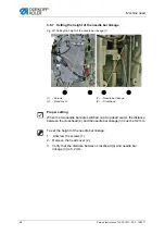
3.8.7 Setting the height of the needle bar linkage
Fig. 28: Setting the height of the needle bar linkage (1)
Proper setting
When the two needle bars are switched on at top dead center, the distance
between the crosshead (4) and the needle bar linkage (3) must be 0.2 mm.
To set the height of the needle bar linkage:
1.
Unscrew the screws (1).
2.
Remove the head cover (2).
3.
Verify that the distance between crosshead (4) and needle bar
linkage (3) is 0.2 mm.
(1)
- Screws
(2)
- Head cover
(3)
- Needle bar linkage
(4)
- Crosshead
①
②
③
④
Summary of Contents for 745-35-10 D
Page 1: ...745 35 10 D Service Instructions...
Page 6: ...Table of Contents 4 Service Instructions 745 35 10 D 00 0 10 2017...
Page 10: ...About these instructions 8 Service Instructions 745 35 10 D 00 0 10 2017...
Page 74: ...Machine head 72 Service Instructions 745 35 10 D 00 0 10 2017...
Page 84: ...Transport carriage 82 Service Instructions 745 35 10 D 00 0 10 2017...
Page 116: ...Light barriers 114 Service Instructions 745 35 10 D 00 0 10 2017...
Page 122: ...Aligning the machine head 120 Service Instructions 745 35 10 D 00 0 10 2017...
Page 128: ...Folder 126 Service Instructions 745 35 10 D 00 0 10 2017...
Page 146: ...Throw over stacker 144 Service Instructions 745 35 10 D 00 0 10 2017...
Page 282: ...Programming 280 Service Instructions 745 35 10 D 00 0 10 2017...
Page 292: ...Maintenance 290 Service Instructions 745 35 10 D 00 0 10 2017...
Page 294: ...Decommissioning 292 Service Instructions 745 35 10 D 00 0 10 2017...
Page 296: ...Disposal 294 Service Instructions 745 35 10 D 00 0 10 2017...
Page 308: ...Troubleshooting 306 Service Instructions 745 35 10 D 00 0 10 2017...
Page 337: ......


