


5 | Installation
D-R 290
89
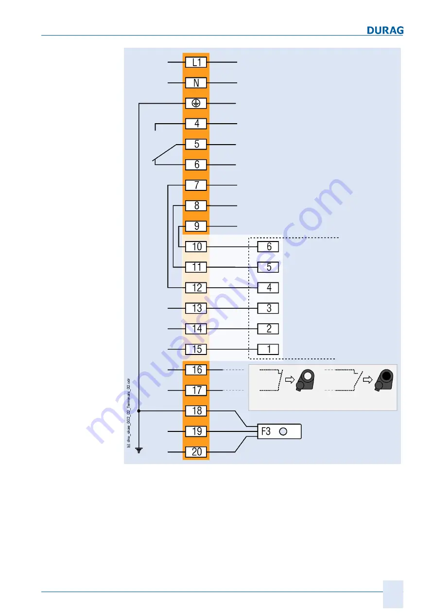
Mains (see type label)
Protective earth conductor
Purge air IN
Purge air OUT
Limit position fail-safe shutter OPEN
Limit position fail-safe shutter CLOSED
Connection strip
to the drive
D-SK 310 MA / D-SK 290 MA
. D-SK 280 MA
external
Close shutter
Air flow sensor
sw
br
gr
no
no
no
nc
c
c
Fig. 5.22: Electrical connection to the D-SK AE
5 cable glands are available for connection of the cables. The M20 cable glands are
suitable for cable diameters from 7 mm to 13 mm. The M16 cable glands are used for
cable diameters between 4.5 mm and 10 mm.
The cables for the mains and data cables should be routed separately.
The mains supply cable should use H 07 RR – U 3 G 1.5 or the equivalent. The mate
rial of the conductors and sheath must be appropriate to the conditions at the operat
ing site. To protect the supply conductor, a 16 A automatic circuit breaker should be
installed as near to the measuring system as possible. Label the MCB so that it can be
Summary of Contents for D-R 290
Page 12: ...12 D R 290 ...
Page 18: ...1 General 18 D R 290 ...
Page 20: ...20 D R 290 ...
Page 28: ...2 Safety 28 D R 290 ...
Page 30: ...30 D R 290 ...
Page 38: ...3 Delivery 38 D R 290 ...
Page 40: ...40 D R 290 ...
Page 60: ...4 Product description 60 D R 290 ...
Page 106: ...106 D R 290 ...
Page 152: ...152 D R 290 ...
Page 174: ...8 Maintenance 174 D R 290 ...
Page 176: ...176 D R 290 ...
Page 178: ...9 Appendix 178 D R 290 Fig 9 2 Measurement point questionnaire 2 ...
Page 194: ...9 Appendix 194 D R 290 ...
Page 200: ...11 Index 200 D R 290 ...
Page 202: ...GmbH Kollaustraße 105 22453 Hamburg Germany www durag com ...


