24
Chapter 2
Description of the Operation
z
Scanner Section...........................................................26
1. Description...............................................................26
2. Sequence of Operation ...........................................27
(1) Sequence of the Scanner Operation ..................27
(2) Sequence of the Scanner Operation (S3-ADF)..27
(3) Operation with the Document
Cover Open / Closed ..........................................28
1. Reading the Document Size...........................28
2. Reading the Document Darkness..................28
2
Platemaking Area for the Selected Paper.....29
2
Platemaking Area for the Book Shadow
Erasing Mode..................................................29
3. Function of Parts and Circuit.............................30
(1) Slider Limit Sensors 1, 2....................................30
(2) Document Size Sensor........................................31
(3) Document Cover Open/Close Sensor.................33
(4) CCD / Lamps ......................................................34
(5) Scanner Unit Open / Close Detection................35
x
Platemaking / Master Feed / Ejection Section...........36
Platemaking / Master Feed Section
........................40
1. Description...............................................................40
2. Sequence of Operation ...........................................41
(1) Operation when the master set ........................41
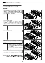
(2) Platemaking / Master Feeding ..........................42
3. Function of Parts ....................................................43
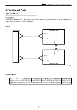
(1) Thermal Head.....................................................43
(2) End Mark Sensor ...............................................46
1. Master Setting Error Detection ......................47
2. Master End Detection......................................47
(3) Master top sensor ...............................................48
(4) Drum Master Sensor .........................................49
(5) Cutter Unit .........................................................50
(6) Master Feed Clutch (Electromagnetic clutch)..51
Master Ejection Section
...........................................52
1. Description...............................................................52
2. Circuit .......................................................................52
3. Function of Parts ....................................................53
(1) Master Ejection Sensor ......................................53
1. Master Ejection Error Detection.....................53
2. Rotation Control of the Eject(Roll-up) Motor .........53
Master Clamp Opening/Closing Section
...............54
1. Description...............................................................54
2. Operation of Master Clamp Open / Close Lever ........55
(1) Structure.............................................................55
(2) Master Attach / Detach Operation ....................56
(3) Clamp Opening / Closing
Lever Position (B / C Mode)...............................57
3. Function of Parts ....................................................58
(1) B / C Mode Detect Sensor ..................................58
4. Returning Operation Flowchart
When the Power is Cut Off Accidentally ...............59
c
Paper Feed Section .....................................................60
1. Description...............................................................60
2. Operation .................................................................61
(1) Rotation of the Paper Feed Roller and
Timing Roller .....................................................61
(2) Paper Feed Roller Drive.....................................62
(3) Driving of the Timing Roller..............................63
(4) Escape the Guide Roller.....................................64
(5) Paper Feed Length .............................................65
3. Function of Parts .....................................................66
(1) Printing Position Adjustment Mechanism .......66
(2) Double Feed Detect Mechanism ........................68
(3) Elevator Top Limit Sensor .................................69
(4) Elevator Lower Limit Switch ............................70
(5) Paper Sensor.......................................................71
Summary of Contents for DP-S Series
Page 1: ......
Page 9: ......
Page 11: ......
Page 16: ...x Dimensions chap 1 15 R8S01001 xDimensions 622 1360 510 228 1080 710 980 688 370 mm...
Page 22: ...v Part Names and Their Functions chap 1 21 44000A1e 2A 2B 2C R8S01006a 2Detailed drawing...
Page 33: ...32 z Scanner Section chap 2 Circuit R8S02E03e...
Page 87: ...86 m Drum Section chap 2 2 Circuit R8S02E30...
Page 171: ...170 MEMO...
Page 193: ...192 MEMO...
Page 195: ...194 z Help mode List chap 7 z HELP Mode List...
Page 243: ...242 c HELP Mode Function and Operation Procedures chap 7...
Page 270: ...269 c HELP Mode Function and Operation Procedures chap 7...
Page 281: ...280 MEMO...
Page 293: ...292 z Electrical Parts Layout and Their Functions chap 9 MEMO...
Page 295: ...309 294 x Overall Wiring Layout chap 9 Overall Wiring Layout 1 Main PCB 2 2...
Page 297: ...311 296 x Overall Wiring Layout chap 9 Overall Wiring Layout 2 Drive PCB 2 2...


