background image

7. Connecting to a Network

112

7-2. Connecting to MultiPresenter

Preparations:

When connecting the projector to a wired LAN, connect a LANcable to the unit. (

 page 

91

)

When connecting the projector to a wireless LAN, install a separately-sold LAN unit in the 
unit. (

 page 

93

)

Configure the [NETWORK SETTINGS] of the projector. (

 page 

114

)

Install the MultiPresenter app in the computer or tablet terminal

.

See Dukane website Downloads for this model to get link for MultiPresenter

The procedure is described here for each wireless LAN profile [INTELLIGENT CONNECTION], [INFRA-
STRUCTURE], and [SIMPLE ACCESS POINT].

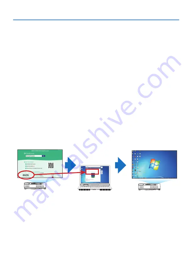
 When connecting with an [INTELLIGENT CONNECTION]

1. Turn on the power of the projector and press the APPS button on the remote controller.

The start-up screen of MultiPresenter is displayed.

2. Start MultiPresenter.

The target device screen is displayed.

3. Enter the 4-digit PIN code displayed in the start-up screen in the target device screen.

When connection with the projector is completed, the screen of the computer or tablet terminal
is projected on the screen.

Summary of Contents for 6652WSSB

Page 1: ...6652WSSB 6652WUSSB 6660WUSSB User s Manual Please visit our web site for User s Manual in the latest version Model No 6652WSSB 6652WUSSB 6660WUSSB http www dukaneav com 6652WSSB_6652WUSSB_6660WUSSB_User Manual 00 ...

Page 2: ...gnal Automatically 32 2 8 Turning Up or Down Volume 32 2 9 Turning off the Projector 33 2 10 When Moving the Projector 34 3 Convenient Features 35 3 1 Turning off the Image and Sound 35 3 2 Freezing a Picture 35 3 3 Magnifying a Picture 36 3 4 Changing Eco Mode Checking Energy Saving Effect 37 3 5 Correcting distortion of projected image 39 3 6 Preventing the Unauthorized Use of the Projector SECU...

Page 3: ...und image 109 7 Connecting to a Network 111 7 1 Things you can do by connecting the projector to a network 111 7 2 Connecting to MultiPresenter 112 7 3 NETWORK SETTINGS 114 7 4 HTTP server function 120 8 Maintenance 124 8 1 Cleaning the Lens 124 8 2 Cleaning the Cabinet 125 9 Appendix 126 9 1 Setting Up the Screen and the Projector 126 9 2 Compatible Input Signal List 130 9 3 Specifications 132 9 ...

Page 4: ...lieve the projector may be faulty Ver 3 3 19 NOTES 1 The contents of this user s manual may not be reprinted in part or whole without permission 2 The contents of this user s manual are subject to change without notice 3 Great care has been taken in the preparation of this user s manual however should you notice any questionable points errors or omissions please contact us 4 Notwithstanding articl...

Page 5: ...this symbol and handling the product erroneously could result in personal injury or damage to surrounding property Examples of symbols This symbol indicates you should be careful of electric shocks This symbol indicates you should be careful of high temperatures This symbol indicates something that must be prohibited This symbol indicates something that must not be got wet This symbol indicates yo...

Page 6: ...er cord please check rated voltage for your region by yourself AC 230 V European countries AC 120 V North America PROHIBITION The power cord included with this projector is exclusively for use with this projector For safety do not use it with other devices HAZARDOUS VOLTAGE Handle the power cord with care Damaging the cord could lead to fire or electric shock Do not place heavy objects on the cord...

Page 7: ...the projector first turn off the projector s power then unplug the power cord from the power outlet and contact your dealer UNPLUGTHE POWER CORD Do not insert or drop metal or combustible objects or other foreign materials into the projector from the vents Doing so could lead to fire or electric shock Beparticularlycarefuliftherearechildreninthehome Shouldaforeignobject get inside the projector fi...

Page 8: ...mounting device and installation location When installed suspended from the ceiling etc do not hang from the projec tor The projector could drop and cause injury When installing suspended from the ceiling use a power outlet that is within reach so the power cord can be easily plugged and unplugged Do not place objects in front of the lens while the projector is operating PROHIBITION Do not leave t...

Page 9: ... no one looking at the lens within the projection range before turning on the projector Donotallowchildrentooperatetheprojectoralone Whenachildisoperating the projector an adult should always be present and watch the child carefully The below pictogram that is indicated near the lens on the cabinet describes this projector is categorized in the risk group 2 of IEC 62471 5 2015 As with any bright l...

Page 10: ...ector first be sure to turn off the power unplug the power cord from the power outlet and check that all connection cables con necting the projector to other devices have been disconnected When planning not to use the projector for long periods of time always unplug the power cord from the power outlet Do not use on networks subject to overvoltage PROHIBITION Connect the projector s Ethernet HDBas...

Page 11: ... where the projector is installed and its surroundings as a general rule at least 10 cm 4 inches for the intake vent 20 cm 8 inches for the exhaust vent Do not touch the exhaust vent area while projecting or immediately after projecting images The exhaust vent area may be hot at this time and touch ing it could cause burns CAUTION FOR HIGH TEMPERATURE Moving the projector PROHIBITION When moving t...

Page 12: ... your country in relation to the installation and management of the device Outline of laser emitted from the built in light module Wave length 449 461 nm Maximum power 100 W 6660WUSSB 82 5 W 6652WUSSB 6652WSSB Radiation pattern from the protective housing Wave length 449 461 nm Maximum laser radiation output 66 6 mW The laser module is equipped in this product Use of controls or adjustments of pro...

Page 13: ...tion and the explanatory labels of the LASER PRODUCT in CLASS 2 conforming to IEC 60825 1 Second edition and in Class 1 conforming to IEC 60825 1 Third edition are stuck on the below indicated positions For USA Label For other regions ...

Page 14: ... the laser light Horizontal angle unit degree Zoom Lens position Right most Center Reference value Left most HR HC HL Wide 33 0 22 3 33 0 Tele 21 8 14 2 21 8 HC HR HL HC Left Right Vertical angle unit degree Zoom Lens position Upper most Center Reference value VU VC Wide 29 5 14 4 Tele 19 2 9 0 VC VC VU Upper ...

Page 15: ...er there is no guarantee that interference will not occur in a particular installation If this equipment does cause harmful interference to radio or television reception which can be determined by turning the equipment off and on the user is encouraged to try to correct the interference by one or more of the following measures Reorient or relocate the receiving antenna Increase the separation betw...

Page 16: ...al and electronic products only applies to the current European Union Member States Outside the European Union If you wish to dispose of used electrical and electronic products outside the European union please contact your local authority and ask for the correct method of disposal For EU The crossed out wheeled bin implies that used batteries should not be put to the general household waste There...

Page 17: ...gh altitudes places where the atmospheric pressure is low it may be necessary to replace the optical parts light source etc sooner than usual About moving the projector Be sure to mount the included lens cap to protect the lens from scratches Do not subject the projector to vibrations or strong shocks The projector could be damaged otherwise Do not use the tilt feet for purposes other than adjusti...

Page 18: ...ector may be taken back in Also make sure no wind from an air conditioner hits the projector The projector s heat control system may detect an abnormality temperature error and automati cally shut off the power 20 cm 8 or greater Exhaust vent Wall NOTE In the above figure it is assumed that there is sufficient space above the projector There is also an intake vent on the back Leave about 10 cm or ...

Page 19: ... below To control the projector from an external device via a LAN or serial cable connection use the on screen menu to change the settings for 1 and 2 1 STANDBY MODE Factory preset NORMAL To control the projector from an external device select NETWORK STANDBY or SLEEP for STANDBY MODE page 79 2 AUTO POWER OFF Factory preset 1 hour To control the projector from an external device select OFF for AUT...

Page 20: ...demark and logo are trademarks applied for registration or are already registered in Japan the United States of America and other countries and areas Wi Fi is a registered trademark of the Wi Fi Alliance WPA WPA2 are trademarks of the Wi Fi Alliance Blu ray is a trademark of Blu ray Disc Association CRESTRON and CRESTRON ROOMVIEW are trademarks or registered trademarks of Crestron Electronics Inc ...

Page 21: ...nt design utilizing a sealed structure A silent design with no irritating fan noise even in a quiet conference room or classroom Light source Brightness A long life laser diode is equipped in the light module The product can be operated at low cost because the laser light source can be used for a long time without requiring replacement or maintenance Brightness can be adjusted within a wide range ...

Page 22: ...of input terminals HDMI 2 HDBaseT etc Theprojectorisequippedwithavarietyofinputterminals HDMI 2 Computer analog Video HDBaseT etc HDMI input terminal on this product supports HDCP HDBaseT is a connection standard for home appliances that is established by the HDBaseT Alliance Simultaneous display of 2 images PIP With this projector it is possible to project 2 images with a single projector by disp...

Page 23: ...jector Compatible with the MultiPresenter application This projector is compatible with the NEC MultiPresenter application so multi screen projection is possible via the network wired LAN wireless LAN Energy saving 0 13 W 100 130 V AC 0 19 W 200 240 V AC in standby condition with energy saving technology Selecting NORMAL for STANDBY MODE from the menu can put the projector in power saving mode NOR...

Page 24: ...missing contact your dealer Please save the original box and packing materials if you ever need to ship your projector Projector Remote control 7N901171 Batteries AAA 2 Power cord US 7N080236 7N080242 EU 7N080022 7N080028 Computer cable VGA 7N520089 Lens cap strap Information sheet Security Sticker Use this sticker when security password is set on ...

Page 25: ...ens Cap 6 Indicators page 8 145 7 Remote Sensor page 14 8 Monaural Speaker 9 Controls page 8 10 Security Slot 11 Security chain opening Attach an anti theft device Thesecuritychainopeningacceptssecurity wires or chains up to 0 18 inch 4 6 mm in diameter 12 Tilt Foot page 27 TIP Security and theft protection lock compatible with Kensington security cables equipment For products visit Kensington s w...

Page 26: ...s 6 Mounting the lens cap strap 1 Insert the tip of the strap into the lens cap mount hole and pass the knot through Lens cap mount hole 2 Insert the knot into the strap mount hole large on the bottom of the projector then press it into the narrow small hole ...

Page 27: ... items and part names 7 Rear 1 2 3 5 4 1 Terminal Panel page 9 2 AC Input Connect the supplied power cord s three pin plug here and plug the other end into an active wall outlet page 16 3 Intake Vent 4 Remote Sensor page 14 5 Exhaust Vent ...

Page 28: ...ators 8 7 9 4 3 2 5 6 1 1 POWER Button page 18 33 2 POWER Indicator page 16 18 33 145 3 STATUS Indicator page 145 4 LIGHT Indicator page 145 5 INPUT Button page 20 6 MENU Button page 51 7 EXIT Button page 51 8 Volume Buttons Keystone Button page 28 32 51 9 ENTER Button page 51 ...

Page 29: ...sabled 6 Ethernet HDBaseT Port RJ 45 page 95 7 LAN Port RJ 45 page 91 8 USB Port Type A Connect the USB memory When picture data is saved in a USB memory the picture can be projected with the VIEWER of the projector page 100 In addition a 5V 2 0 A power supply can be supplied for expansion use 9 PC CONTROL Port D Sub 9 Pin Use this port to connect a PC or control system This enables you to control...

Page 30: ... 2 POWER ON Button page 18 3 POWER STANDBY Button page 33 4 SOURCE Button page 20 5 HDMI1 Button page 20 6 HDMI2 Button page 20 7 HDBaseT Button page 20 8 DisplayPort Button This button does not work in this series of projec tors 9 COMPUTER Button page 20 10 AUTO ADJ Button page 32 11 VIDEO Button This button does not work in this series of projec tors ...

Page 31: ... 20 101 13 USB B Button This button does not work in this series of projec tors 14 APPS Button page 20 112 15 ID SET Button page 75 16 Numeric Keypad Button CLEAR Button page 75 17 PIP Button page 48 18 FREEZE Button page 35 19 AV MUTE Button page 35 20 MENU Button page 51 21 EXIT Button page 51 22 Button page 36 51 ...

Page 32: ...on does not work in this series of projec tors 26 MOUSE R CLICK Button This button does not work in this series of projec tors 27 PAGE Button page 105 107 28 ECO Button page 37 29 KEYSTONE Button page 28 39 30 PICTURE Button page 58 61 31 VOL Button page 32 32 ASPECT Button page 64 33 FOCUS ZOOM Button This button does not work in this series of projec tors 34 HELP Button page 83 ...

Page 33: ...and old batteries OPEN Remote Control Precautions Handle the remote control carefully If the remote control gets wet wipe it dry immediately Avoid excessive heat and humidity Do not short heat or take apart batteries Do not throw batteries into fire If you will not be using the remote control for a long time remove the batteries Ensure that you have the batteries polarity aligned correctly Do not ...

Page 34: ...ote control The infrared signal operates by line of sight up to a distance of about 23 feet 7 m and within a 60 degree angle of the remote sensor on the projector cabinet The projector will not respond if there are objects between the remote control and the sensor or if strong light falls on the sensor Weak batteries will also prevent the remote control from properly operating the projector ...

Page 35: ...ector page 18 Step 3 Selecting a source page 20 Step 4 Adjusting the picture size and position page 22 Correcting keystone distortion KEYSTONE page 28 Step 5 Adjusting a picture and sound Optimizing a computer signal automatically page 32 Turning up or down volume page 32 Step 6 Making a presentation Step 7 Turning off the projector page 33 Step 8 When Moving the Projector page 34 2 Projecting an ...

Page 36: ...ct the supplied power cord s three pin plug to the AC IN terminal of the projector and then connect another plug of the supplied power cord directly in the wall outlet Do not use any plug converter CAUTION This equipment is designed to be used in the condition of the power cord connected to earth If the power cord is not connected to the earth it may cause electric shock Please make sure the power...

Page 37: ...2 Projecting an Image Basic Operation 17 CAUTION Parts of the projector may become temporarily heated if the projector is turned off with the POWER button Be careful to handle the projector ...

Page 38: ...the projec tor cabinet or the POWER ON button on the remote control The POWER indicator lights blue and the image is projected on the screen TIP When the message PROJECTOR IS LOCKED ENTER YOUR KEYWORD isdisplayed itmeansthatthe SECURITY feature is turned on page 46 Afteryouturnonyourprojector ensurethatthe computer or video source is turned on NOTE When no input signal is present the no signal gui...

Page 39: ... can select the menu language later LANGUAGE on page 54 and 68 NOTE If one of the following things happens the projector will not turn on If the internal temperature of the projector is too high the projector detects abnormal high temperature In this condition the projector will not turn on to protect the internal system If this happens wait for the projector s internal components to cool down If ...

Page 40: ...e projector will search for the available input source and display it The input source will change as follows HDMI1 HDMI2 COMPUTER HDBaseT USB A LAN Withthe INPUT screendisplayed youcanpress theINPUTbuttonafewtimestoselecttheinput source Press the SOURCE button when using the re mote control TIP If no input signal is present the input will be skipped Using the Remote Control Press any one of the H...

Page 41: ... button The DEFAULT INPUT SELECT screen will be displayed 5 Select a source as the default source and press the ENTER button 6 Press the EXIT button a few times to close the menu 7 Restart the projector The source you selected in step 5 will be projected TIP Whentheprojectorandcomputerareconnectedandtheprojectorisinstandby itispossibletoturnontheprojector spowerand project the computer s screen au...

Page 42: ...he picture size and position In this chapter drawings and cables are omitted for clarity Adjusting the projected image s vertical and horizontal position Lens shift page 23 Adjusting the focus Focus ring page 25 Finely adjusting the size of an image Zoom lever page 26 Adjusting the projected image s height and horizontal tilt Tilt foot page 27 Correcting the keystone distortion Keystone page 28 ...

Page 43: ... the lens shift cover Open with the cover s stopper pushed forward The lens shift cover cannot be removed Stopper 2 Turn the lens shift dials clockwise or counterclockwise Vertical dial Turnthisclockwiseorcounterclockwisetoadjusttheprojectionpositionintheverticaldirection Horizontal dial Turn this clockwise or counterclockwise to adjust the projection position in the horizontal direction Lens shif...

Page 44: ... finish the vertical shift adjustment with an image shifted down the zoom focus adjustments or strong shaking may cause a projected image to slightly shift down 3 Close the lens shift cover Insertthecover s2 two hooksintothegrooves in the projector then close the cover Hook Groove TIP The diagram below shows the lens shift adjustment range ORIENTATION DESKTOP FRONT For the lens shift adjustment ra...

Page 45: ... 25 Focus Use the focus ring to obtain the best focus Focus ring NOTE RecommendtoperformthefocusadjustmentafterleavingtheprojectorunderthestatetheTESTPATTERNhasbeenprojectedfor over 30 minutes Please refer to page 76 about theTEST PATTERN ...

Page 46: ...2 Projecting an Image Basic Operation 26 Zoom Turn the zoom lever clockwise and counterclockwise Zoom lever ...

Page 47: ...mage is distorted see 2 6 CorrectingKeystoneDistortion KEYSTONE page 28 The tilt feet can be lengthened by a maxi mum of 15 mm 0 6 The tilt feet can be used to tilt the projector by a maximum of 2 Up Down Tilt foot NOTE Donotlengthenthetiltfeetanymorethan15mm 0 6 Doingsowillmakethetiltfeet smountsectionunstableandcouldcause the tilt feet to come off the projector Do not use the tilt feet for any p...

Page 48: ...E VERTICAL PINCUSHION LEFT RIGHT PINCUSHION TOP BOTTOM and CORNERSTONE If the value of either CORNERSTONE or PINCUSHION has corrected KEYSTONE HORIZONTAL and KEYSTONE VERTICAL are disabled In this case RESET the corrected values and restart to correct distortion 1 Pressthe buttonontheprojectorcabinet The GEOMETRIC CORRECTION screen will be displayed on the screen Press the KEYSTONE button when usi...

Page 49: ...he left or right side of the projected image Use the shorter side of the projected im age as the base In the right example use the left side as the base Align left side 7 Press the button to select KEYSTONE HORIZONTAL and then use the or so that the top and bottom sides of the pro jected image are parallel Adjust the horizontal keystone distortion 8 Repeat steps 5 and 7 to correct keystone distort...

Page 50: ...mage Basic Operation 30 NOTE Even when the projector is turned on the last used correction values are applied The KEYSTONE feature can cause an image to be slightly blurred because the correction is made electronically ...

Page 51: ...METRIC CORRECTION screen and make sure KEYSTONE is selected at MODE 2 Press the button to select RESET and press the ENTER button 3 Press the or button to select YES and press the ENTER button The adjustments will be reset NOTE All adjusted values set in the KEYSTONE adjustment are reset to initial values ...

Page 52: ...If the Auto Adjust operation cannot optimize the computer signal try to adjust HORIZONTAL VERTICAL CLOCK and PHASE manually page 62 63 2 8 Turning Up or Down Volume Sound level from the speaker or audio output can be adjusted When no menus appear the and buttons on the projector cabinet work as a volume control On the remote control press the VOL or button NOTE Volumecontrolisnotavailablewiththe o...

Page 53: ...tion this session page 38 2 Secondly press the ENTER button or press the POWER or the STANDBY button again Whenthelightsourceturnsoff thepowerturns off too standby mode When the projector goes into the standby mode the POWER indicator of the unit flashes orange In the state STANDBY MODE is NORMAL Power On Steady blue light Standby Blinking orange light 3 Mount the lens cap Insert the cap s 2 two h...

Page 54: ... or from the power outlet while an image is being projected Doing so could deteriorate the projector s AC IN terminal or the power plug s contact To turn off the AC power while an image is being projected use the power strip s switch the breaker etc Do not disconnect the AC power supply to the projector within 10 seconds of making adjustment or setting changes and closing the menu Doing so can cau...

Page 55: ... sound NOTE Even though the image is turned off the menu still remains on the screen 3 2 Freezing a Picture Press the FREEZE button If the image of a DVD player etc is being projected the video switches to a still image Press the FREEZE button again to resume the video NOTE The image is frozen but the original video is still playing back 3 Convenient Features ...

Page 56: ...o so 1 Press the D ZOOM button to magnify the picture To move the magnified image use the or button 2 Press the button The area of the magnified image will be moved 3 Press the D ZOOM button Each time the D ZOOM button is pressed the image is reduced NOTE The image will be magnified or demagnified at the center of the screen Displaying the menu will cancel the current magnification ...

Page 57: ... button The ECOMODE selectionscreenturnsoffand the projector switches to the selected mode NOTE The ECO MODE can be changed by using the menu Select SETUP GENERAL LIGHT MODE ECO MODE The LIGHT HOURS USED can be checked in USAGETIME Select INFO USAGETIME Afteralapseof1minutefromwhentheprojectordisplaysno signalguidance ablue blackorlogoscreen theprojectorgoesinto LONG LIFE automatically The project...

Page 58: ...duction between the time of changing to ECO MODE immediately after the time of power on and the time of power off The CARBON SAVINGS SESSION message will be displayed in the POWER OFF AREYOU SURE message at the time of power off TIP The formula as shown below is used to calculate the amount of CO2 emission reduction AmountofCO2 emissionreduction Powerconsumptionin OFF for ECOMODE Powerconsumptioni...

Page 59: ...ither CORNERSTONE or PINCUSHION has corrected KEYSTONE HORIZONTAL and KEYSTONE VERTI CAL are disabled In this case RESET the corrected values and restart to correct distortion Cornerstone 1 Pressthe buttonwithnomenudisplayed The GEOMETRIC CORRECTION screen will be displayed Press the KEYSTONE button when using the remote control 2 Move the cursor onto MODE by button and press the ENTER The mode se...

Page 60: ...to select one icon which points in the direction you wish to move the projected image frame TIP Ifeither CORNERSTONE or PINCUSHION isadjusted the options KEYSTONE VERTICAL and KEYSTONE HORIZON TAL becomeunavailable Inthiscase RESETthecorrected values and restart to correct distortion 9 Press the ENTER button 10 Usethe buttontomovetheproject ed image frame as shown on the example 11 Press the ENTER...

Page 61: ...R button This completes the Cornerstone correction Selecting CANCEL will return to the ad justment screen without saving changes Step 3 Selecting RESET willreturntothefactory default Selecting UNDO will exit without saving changes 14 Press the EXIT button a few times to turn off the menu ...

Page 62: ...e KEYSTONE button when using the remote control 2 Move the cursor onto MODE by button and press the ENTER The mode selection screen will displayed on 3 Select KEYSTONE and press the ENTER Go back to display the GEOMETRIC CORREC TION screen of the on screen menu 4 Press the button to align with the KEY STONE and then press the ENTER button The screen will switch to the KEYSTONE screen 5 Pressthe or...

Page 63: ...RNERSTONE is activated Before performing correction set the lens shift to the center position 7 After completing PINCUSHION adjust ment press the EXIT button a few times to turn off the menu NOTE Even when the projector is turned on the last used correction values are applied PINCUSHION and CORNERSTONE correctionscancausetheimagetobeslightlyblurredbecausethecorrectionismadeelectroni cally ...

Page 64: ...ation message is displayed on 3 Move the cursor onto YES using either or button and then press the ENTER NOTE All adjusted values set in the KEYSTONE adjustment are reset to initial values TIP Distortionwhenprojectingonspeciallyshapedsurfaces cylindricalorsphericalsurfaces forexample canbecorrectedusingour Geometric CorrectionTool application Please download Geometric CorrectionTool from our web s...

Page 65: ...he menu To enable the Security function 1 Press the MENU button The menu will be displayed 2 Press the button twice to select SETUP and press the button or the ENTER button to select GENERAL 3 Press the button to select INSTALLATION 4 Press the button three times to select SECURITY and press the ENTER button The OFF ON menu will be displayed 5 Press the button to select ON and press the ENTER butt...

Page 66: ...n enabled To turn on the projector when SECURITY is enabled 1 Press the POWER button The projector will be turned on and display a message to the effect that the projector is locked 2 Press the MENU button 3 Type in the correct keyword and press the ENTER button The projector will display an image NOTE The security disable mode is maintained until the main power is turned off or unplugging the pow...

Page 67: ... press the ENTER button The SECURITY KEYWORD screen will be displayed 4 Type in your keyword and press the ENTER button When the correct keyword is entered the SECURITY function will be disabled NOTE Ifyouforgetyourkeyword contactyourdealer Yourdealerwillprovideyouwithyourkeywordinexchangeforyourrequestcode YourrequestcodeisdisplayedintheKeywordConfirmationscreen Inthisexample K992 45L8 JNGJ 4XU9 ...

Page 68: ...s the sub display A small sub display is displayed inside the main display Main Display Sub Display Input terminals that can be used for the main display and sub display The main display and sub display can provide the following input terminals Sub Display HDMI1 HDMI2 COMPUTER HDBaseT USB A LAN Main Display HDMI1 No Yes No No No HDMI2 No Yes No No No COMPUTER Yes Yes Yes No No HDBaseT No No Yes No...

Page 69: ... cannot be selected 4 Press the MENU button The on screen menu will disappear 5 When returning to single screen display the PIP screen one more time and select OFF in the SUB INPUT screen of the Step 3 TIP During dual screen projection if the selected input is not supported by the sub screen the sub screen will appear as a blue or black screen The sub display can be set up and adjusted as follows ...

Page 70: ...o magnification compression using the partial D ZOOM buttons Video pause FREEZE The following operations are enabled only for the main display Audio visual adjustments The following operations are enabled for both the main display and sub display These operations cannot be applied individually Momentary deletion of video audio AV MUTE ...

Page 71: ...the item you want to adjust or set You can use the buttons on the remote control or the projector cabinet to select the tab you want 5 Press the ENTER button on the remote control or the projector cabinet to display the submenu window 6 Adjust the level or turn the selected item on or off by using the buttons on the remote control or the projector cabinet Changes are stored until adjusted again 7 ...

Page 72: ...his round button to select an option in a dialog box Source Indicates the currently selected source OffTimer remaining time Indicates the remaining countdown time when the OFFTIMER is preset Slide bar Indicates settings or the direction of adjustment ECO mode symbol Indicates ECO MODE is set Key Lock symbol Indicates the CONTROL PANEL LOCK is enabled Thermometer symbol Indicates the projector is i...

Page 73: ...T 1 7 DETAIL SETTINGS GENERAL REFERENCE HIGH BRIGHT PRESENTATION VIDEO MOVIE GRAPHIC sRGB DICOM SIM GAMMA CORRECTION DYNAMIC NATURAL BLACK DETAIL SCREEN SIZE LARGE MEDIUM SMALL COLORTEMPERATURE DYNAMIC CONTRAST OFF ON IMAGE MODE STILL MOVIE COLOR ENHANCEMENT OFF LOW MEDIUM HIGH WHITE BALANCE CONTRAST R CONTRAST G CONTRAST B BRIGHTNESS R BRIGHTNESS G BRIGHTNESS B CONTRAST B BRIGHTNESS B SHARPNESS B...

Page 74: ...TINA MAGYAR POLSKI NEDERLANDS SUOMI NORSK TÜRKÇE РУССКИЙ ΕΛΛΗΝΙΚΆ 简体中文 한국어 TIẾNG ViỆT ROMÂNĂ HRVATSKI БЪЛГАРСКИ INDONESIA हिन दी ไทย 繁體中文 GEOMETRIC CORRECTION MODE OFF KEYSTONE PCTOOL KEYSTONE KEYSTONE HORIZONTAL KEYSTONEVERTICAL PINCUSHION LEFT RIGHT PINCUSHIONTOP BOTTOM CORNERSTONE PCTOOL OFF 1 2 3 RESET MENU COLOR SELECT COLOR MONOCHROME INPUT DISPLAY OFF ON ID DISPLAY OFF ON ECO MESSAGE OFF ON...

Page 75: ...WER ON OFF AUTO HDMI1 HDMI2 COMPUTER AUTO POWER OFF OFF 0 05 0 10 0 15 0 20 0 30 1 00 DEFAULT INPUT SELECT LAST AUTO HDMI1 HDMI2 COMPUTER HDBaseT USB A LAN CARBON CONVERT CURRENCY JP RMB CURRENCY CONVERT STATIC CONVERGENCE HORIZONTAL R HORIZONTAL G HORIZONTAL B VERTICAL R VERTICAL G VERTICAL B INFO USAGETIME B LIGHT HOURS USED TOTAL CARBON SAVINGS TOTAL COST SAVINGS SOURCE 1 B SOURCE NAME SOURCE I...

Page 76: ...URITY CHANNEL SIGNAL LEVEL VERSION 1 B FIRMWARE DATA VERSION 2 B FIRMWARE2 DATA2 OTHERS B DATETIME B PROJECTOR NAME B HOST NAME B MODEL NO B SERIAL NUMBER B LAN UNITTYPE CONTROL ID when CONTROL ID is set B CONDITIONS INTAKETEMPERATURE EXHAUSTTEMPERATURE INSTALLATION POSITION X AXIS Y AXIS Z AXIS RESET CURRENT SIGNAL ALL DATA ...

Page 77: ... COMPUTER IN terminal signal NOTE When the component input signal is connected to the COMPUTER IN terminal select COMPUTER HDBaseT Projects the signal transmitted from the terminals supported HDBaseT USB A Start the VIEWER Project the data of the USB memory set in this machine LAN Display the start up screen of MultiPresenter Selects a signal from the LAN port RJ 45 or the installed USB wireless L...

Page 78: ...ended for use in a brightly lit room PRESENTATION Recommended for making a presentation using a PowerPoint file VIDEO Recommended for typicalTV program viewing MOVIE Recommended for movies GRAPHIC Recommended for graphics sRGB Standard color values DICOM SIM Recommended for DICOM simulation format NOTE The DICOM SIM option is for training reference only and should not be used for actual diagnosis ...

Page 79: ...lecting Gamma Correction Mode GAMMA CORRECTION Each mode is recommended for DYNAMIC Creates a high contrast picture NATURAL Natural reproduction of the picture BLACK DETAIL Emphasizes detail in dark areas of the picture NOTE This function is not available when DICOM SIM is selected for REFERENCE Selecting Screen Size for DICOM SIM SCREEN SIZE This function will perform gamma correction appropriate...

Page 80: ... Mode IMAGE MODE This function allows you to select the still image mode or the movie mode STILL This mode is for a still image MOVIE This mode is for a movie NOTE This function is available only when HIGH BRIGHT is selected for REFERENCE Enhancing the Color COLOR ENHANCEMENT This allows you to adjust the color density of the image The color of the image will become deeper in the order of LOW MEDI...

Page 81: ...s used as reference Input signal CONTRAST BRIGHTNESS SHARPNESS COLOR HUE COMPUTER HDMI HDBaseT RGB Yes Yes Yes No No COMPUTER HDMI HDBaseT COMPONENT Yes Yes Yes Yes Yes USB A LAN Yes Yes Yes No No Yes Adjustable No Not adjustable RESET The settings and adjustments for PICTURE will be returned to the factory settings with the excep tion of the following Preset numbers and REFERENCE within the PRESE...

Page 82: ...nding that might appear This function adjusts the clock frequencies that eliminate the horizontal banding in the image This adjustment may be necessary when you connect your computer for the first time PHASE Use this item to adjust the clock phase or to reduce video noise dot interference or cross talk This is evident when part of your image appears to be shimmering Use PHASE only after the CLOCK ...

Page 83: ...exttime you project the signal with the same resolution horizontal and vertical frequency its adjustments will be called up and applied To delete adjustments stored in memory from the menu you select RESET CURRENT SIGNAL or ALL DATA and reset the adjustments Selecting Overscan Percentage OVERSCAN This allows you to set the appropriate overscan for an incoming signal When AUTO is selected the over ...

Page 84: ...terbox signal is stretched equally in the horizontal and vertical directions to fit the screen Parts of the displayed image are cropped at the top and bottom edges and therefore not visible NATIVE The projector displays the current image in its true resolution when the incoming computer signal has a lower resolution than the projector s native resolution Example When the incoming signal with the r...

Page 85: ...UDIO Turning Up or Down Sound Adjusts the volume of the projector speaker and AUDIO OUT Stereo Mini Jack TIP Whennomenusappear the and buttonsontheprojectorcabinetandtheVOL buttonsontheremotecontrolworkas a volume control page 32 ...

Page 86: ...tures at the SameTime page 48 for details on the operation SUB INPUT POSITION Select the display position of the sub screen from 4 locations BOTTOM LEFT BOTTOM RIGHT TOP LEFT TOP RIGHT Sub display Main display PICTURE SWAP The videos in the main display and sub display will be switched Sub display video Main display video Sub display video Main display video NOTE When the input terminal of the mai...

Page 87: ...mode optimizes the service life of the light module ADJUST Brightness can be adjusted in 1 increments from 30 to 100 When several projectors are used for multi screen projection the brightness can be adjusted individually on each projector The adjustment is valid when ECO MODE is set to OFF CONSTANT BRIGHTNESS OFF CONSTANT BRIGHTNESS mode will be canceled ON Maintains the brightness that is in eff...

Page 88: ...e remaining time reaches 3 minutes before the projector is turned off the THE PROJECTOR WILL TURN OFF WITHIN 3 MINUTES message will be displayed on the bottom of the screen Setting the date and time DATE AND TIME SETTINGS Display the start up screen of MultiPresenter page 149 Configuring the menu settings ADMINISTRATOR MODE This allows you to select MENU MODE save settings and set a KEYWORD for th...

Page 89: ... KEYSTONEVERTICAL can be adjusted at once To change from one item to another item reset the first item Adjustment values will be overwritten They will not be deleted even when the projector is turned off Using KEYSTONE PINCUSHION and CORNERSTONE correctioncancausetheimagetobeslightlyblurredbecausethecorrection is made electronically KEYSTONE HORIZONTAL Corrects horizontal keystone distortion page ...

Page 90: ...n the projector beforehand The geometric correction data using our Geometric Correction Tool application page 44 is registered here NOTE As electrical correction is carried out in geometric correction the brightness may be affected and the picture quality may be degraded RESET Resets the item selected at MODE on the GEOMETRIC CORRECTION screen The operation differs depending on the mode selected a...

Page 91: ...LAY This option turns on or off the ID number which is displayed when the ID SET button on the remote control is pressed Turning On Off Eco Message ECO MESSAGE This option turns on or off the following messages when the projector is turned on The ECO MESSAGE prompts the user to save energy When OFF is selected for ECO MODE you will get a message to prompt you to set ECO MODE To close the message p...

Page 92: ...E The background color is blue BLACK The background color is black LOGO Display an image as the background NOTE When INPUTDISPLAY isturnedon theno signalguidancepromptingyoutocheckforanavailableinputwillbedisplayedatthe center of the screen regardless of its selection To change the background image to be displayed as a LOGO see Page 109 Your setting will not be affected even when RESET is done fro...

Page 93: ...projection WARNING Should special works be required for example to suspend the projector from the ceiling consult your dealer Never try to install the projector yourself in such cases The projector could drop and cause injury AUTO When the light module is turned ON the inner sensor of the projector detects its installation state either DESKTOP FRONT or CEILING FRONT and then switch its projection ...

Page 94: ...ge 45 NOTE Your setting will not be affected even when RESET is done from the menu Selecting Communication Speed COMMUNICATION SPEED This feature sets the baud rate of the PC Control port D Sub 9P It supports data rates from 4800 to 38400 bps The default is 38400 bps Select the appropriate baud rate for your equipment to be con nected dependingontheequipment alowerbaudratemayberecommendedforlongca...

Page 95: ...lsensorofthe projector change another option The remote control sensor on the back of the projector cannot be used when the separately sold cable cover is mounted on the projector Setting ID to the Projector CONTROL ID You can operate multiple projectors separately and independently with the single remote control that has the CONTROL ID function If you assign the same ID to all the projectors you ...

Page 96: ... to 254 4 Release the ID SET button The updated CONTROL ID screen will be displayed NOTE The IDs can be cleared in a few days after the batteries are run down or removed Accidentallypressinganyoneofthebuttonsoftheremotecontrolwillclearcurrentlyspeci fied ID with batteries removed Using Test Pattern TEST PATTERN Displays the test pattern for adjusting distortion on the screen and the focus at the t...

Page 97: ...LTITUDE cancausethe projector to overheat and the protector could shut down If this happens wait a couple minutes and turn on the projector Using the projector at altitudes approximately 5500 feet 1700 meters or higher can shorten the life of optical components such as the light module Your setting will not be affected even when RESET is done from the menu Selecting Signal Format SIGNAL SELECT Thi...

Page 98: ... to disable the ENHANCED feature of your HDMI equipment or select ENHANCED to improve image contrast and increase detail in the dark areas Setting Audio AUDIO SELECT This selects the audio inputs of the HDMI 1 IN terminal HDMI 2 IN terminal LAN port and Ethernet HDBaseT port of the unit When inputting analog audio connect the audio output terminal of the connected device to the AUDIO IN terminal o...

Page 99: ... the network standby mode The power supply of the projector can be turned on using a wired LAN LAN port The POWER indicator lights up in orange When NETWORK STANDBY is selected only the following buttons terminals and features will work POWER button on the projector cabinet and the remote control powering on from PC Control command AUTO POWER ON NETWORK SERVICE Power consumption Medium SLEEP The p...

Page 100: ...e will not be included in calculating CO2 emission reduction Your setting will not be affected even when RESET is done from the menu Enabling Direct Power On DIRECT POWER ON Turns the projector on automatically when the power cord is inserted into an active power outlet ThiseliminatestheneedtoalwaysusethePOWERbuttonontheremotecontrolorprojectorcabinet Turning On the Projector By Applying Computer ...

Page 101: ...any one of its inputs each time the projector is turned on LAST Sets the projector to default to the previous or last active input each time the projector is turned on AUTO Searches for an active source in order of HDMI1 HDMI2 COMPUTER HDBaseT USB A LAN and displays the first found source HDMI1 Displays the digital source from the HDMI 1 IN terminal every time the projector is turned on HDMI2 Disp...

Page 102: ... Japanese Yen are based on Energy Prices and Taxes second quarter 2010 published by OECD The initial setting for Chinese Yuan is based on Chinese Data File 2010 published by JETRO Adjusting the color shift of the screen STATIC CONVERGENCE This features allows you to adjust for color deviation in the picture Thiscanbeadjustedinunitsof 1pixelinthehorizontaldirectionfor HORIZONTALR HORIZONTAL G and H...

Page 103: ...OTAL COST SAVINGS TOTAL CARBON SAVINGS This displays the estimated carbon saving information in kg The carbon footprint factor in the carbon saving calculation is based on the OECD 2008 Edition page 38 SOURCE 1 SOURCE NAME SOURCE INDEX HORIZONTAL FREQUENCY VERTICAL FREQUENCY SYNC TYPE SYNC POLARITY SCAN TYPE SOURCE 2 SIGNAL TYPE VIDEOTYPE BIT DEPTH VIDEO LEVEL HDBaseT SIGNAL QUALITY OPERATION MODE...

Page 104: ...row direction of the Z AXIS in the figure represents the top of the projector X AXIS Display the projector image at an angle of 100 100 degrees to the horizontal in the X axis direction X AXIS value of the projector Horizontal plane X axis Gravity direction Y AXIS Display the projector image at an angle of 100 100 degrees to the horizontal in theY axis direction Y AXIS value of the projector Horiz...

Page 105: ... HUE SHARPNESS ASPECT RATIO HORIZONTAL VERTICAL CLOCK PHASE and OVERSCAN ALL DATA Reset all the adjustments and settings for all the signals to the factory preset All items can be reset EXCEPT KEYSTONE HORIZONTAL KEYSTONE VERTICAL PINCUSHION PC TOOL DATE AND TIME SETTINGS ADMINISTRATOR MODE LANGUAGE BACKGROUND ORIENTATION SECURITY COMMUNICATION SPEED SERIAL PORT CONTROL ID NETWORK SETTINGS FAN MOD...

Page 106: ...with the projector Please get ready a suitable cable for the connection NOTE Signals supported by Plug Play DDC2 INPUT COMPUTER IN HDMI 1 IN HDMI 2 IN analog digital digital Yes Yes Yes NOTE An image may not be displayed correctly when aVideo source is played back via a commercially available scan converter This is because the projector will process a video signal as a computer signal at the defau...

Page 107: ...n the cable supplied NOTE For Mac use a commercially available pin adapter not supplied to connect to your Mac s video port Stereo mini plug audio cable not supplied HDMI cable not supplied Use High Speed HDMI Cable Select the source name for its appropriate input terminal after turning on the projector Input terminal INPUT button on the projector cabinet Button on the remote control HDMI 1 IN HDM...

Page 108: ... the display may not be correct during fast forwarding and rewinding UseaDVI to HDMIcablecompliantwithDDWG DigitalDisplayWorkingGroup DVI DigitalVisualInterface revision1 0standard The cable should be within 197 5 m long Turn off the projector and the PC before connecting the DVI to HDMI cable To project a DVI digital signal Connect the cables turn the projector on then select the HDMI input Final...

Page 109: ...layer to the audio components COMPUTER IN AUDIO IN 15 pin to RCA female 3 cable adapter ADP CV1E Stereo mini plug to RCA audio cable not supplied Component video RCA 3 cable not supplied Audio cable not supplied DVD player Audio Equipment Select the source name for its appropriate input terminal after turning on the projector Input terminal INPUT button on the projector cabinet Button on the remot...

Page 110: ...ng on the projector Input terminal INPUT button on the projector cabinet Button on the remote control HDMI 1 IN HDMI1 HDMI1 HDMI 2 IN HDMI2 HDMI2 When connecting the HDMI 1 IN terminal or HDMI 2 IN terminal of the projector to the DVD player the projector s video level can be made settings in accordance with the DVD player s video level In the menu select HDMI SETTINGS VIDEO LEVEL and make necessa...

Page 111: ...LAN you can use the web browser on a computer to control the projector using the HTTP server function For more information see 7 Connecting to a Network page 111 Example of LAN connection Example of wired LAN connection LAN Server Hub LAN cable not supplied NOTE Use a Category 5 or higher LAN cable ...

Page 112: ...elessLANUnitintheareawheretheuseofwirelessLANequipmentisprohibited remove the USBWireless LAN Unit from the projector Buy the appropriate USBWireless LAN Unit for your country or area NOTE Do not press the button on the USBWireless LAN Unit The button does not work with this model Your computer s wireless LAN adapter or unit must be complied withWi Fi IEEE802 11a b g n standard Example of wireless...

Page 113: ...SBWirelessLANunitwhenthemainpoweristurnedoff Failuretodosomaycauseprojectormalfunc tion or damage to the USB wireless LAN unit If the projector will not work correctly turn off the projector disconnect the power cord and then connect it again DonotinsertotherUSBdevicesintotheUSB wirelessLAN portinthewirelessLANcover DonotinserttheUSBWirelessLANunit into the USB port NOTE When the cable cover is at...

Page 114: ...he insertion slot as you push the unit in NOTE Do not force to insert the USBWireless LAN Unit W IR E L E S S W IR E L E S S 4 Mount the wireless LAN cover 1 Insert the hook on the back of the cover into the groove in the projector and close the wireless LAN cover Hook Groove 2 Turn the screw clockwise to tighten it To remove the USB Wireless LAN Unit dis connect the power cord and use the above p...

Page 115: ...Ethernet HDBaseT port of the projector RJ 45 to a HDBaseT transmission device sold commercially The Ethernet HDBaseT port of the projector supports HDMI signals HDCP from transmission de vices control signals from external devices serial LAN and remote control signals IR commands Connection example Ethernet HDBaseT Computer for control use Computer for output use Example of a transmission device R...

Page 116: ...cable is 100 m the maximum distance is 70 m for a 4K signal Short cable such as 0 5 m is not applicable in HDBaseT Projector installations Please do not use other transmission equipment between the projector and transmission equipment The picture quality may be deteriorated as a result This projector is not guaranteed to work with all HDBaseT transmission devices sold commercially ...

Page 117: ...e vent or the exhaust vent may be obstructed resulting in the projector get ting warm and the possibility of fire and malfunction occurring Astandforsupportingtheprojectorneedstobemadeforthispurpose Inthiscase thestand must be designed such that the center of gravity of the projector is located well within the legs of the stand If not the projector may fall over and result in injury damage and mal...

Page 118: ...rojector exhaust vent and the floor Do not obstruct the intake vent at the rear of the projector 2 Use the four screw holes on the bottom face of the projector to secure it to the stand Screw hole center dimension 200 250 mm Screw hole dimension on the projector M4 with a maximum depth of 8 mm Please design the stand such that the rear legs on the bottom face of the projector do not contact the st...

Page 119: ...ents is not an actual stand design drawing Side View Front View Screw holes for 4 M4 use Notch 200 Horizontal adjuster Installation facing the exhaust vent downward maintain a distance of at least 200 mm between the projector Exhaust vent and the floor Unit mm 250 Intake vent Exhaust Vent ...

Page 120: ...stone correction using the buttons is not possible To perform keystone correction when the VIEWER is being displayed press the MENU button 2 times to display the on screen menu When the VIEWER is being displayed the FREEZE button on the remote controller does not work When you select RESET ALL DATA in the on screen menu the option menu settings of the VIEWER return to the default state when shippe...

Page 121: ...tor press the MENU button in the file list screen or DRIVE LIST screen and select REMOVE USB DEVICE Page 103 Remove the USB memory 3 Press the INPUT button The INPUT screen is displayed Press the SOURCE button when using the remote control 4 PresstheINPUTbuttonafewtimesandmove the cursor to USB A Every time the INPUT button is pressed briefly the cursor moves to the next input terminal Move the cu...

Page 122: ... file list screen then press the ENTER button The slide screen will be displayed 8 Press the button The next image will be projected 9 Press the button The previous image will be projected 10 Press the MENU button The control bar will be displayed Press the MENU button while the control barisbeingdisplayedtodisplaythe INPUT screen When you press the MENU button again the INPUT screen disappears Wh...

Page 123: ...to the picture to be displayed in the slideshow and press the ENTER button Remove the USB memory 1 Press the MENU button in the file list screen A pop up menu will be displayed at the bottom left of the screen Press the MENU button while the pop up menu is being displayed to display the INPUT screen When you press the MENU button again the INPUT screen disap pears When you press the EXIT button wh...

Page 124: ...tly wait for about 3 minutes before connecting the power cord to the socket and turning on the power of the unit USB End the VIEWER 1 Press the MENU button in the slide screen or file list screen A control bar or a pop up menu will be dis played 2 Press the MENU button again The INPUT screen is displayed 3 Move the cursor to an input terminal other than USB A and press the ENTER button The VIEWER ...

Page 125: ...MENU Display the control bar On the control bar press the button to move the yellow cursor and press the ENTER button at the desired item The function of each item is as follows Items on the control bar Description Back Project the previous picture Play Stop Start automatic playback of the slideshow Or stop the slide show Next Project the next picture Rotate 90 to the right Rotate the picture cloc...

Page 126: ... thumbnail display Display pictures and folders as icons or thumbnails zoom out Filename of the selected picture Display the file name of the picture corresponding to the cursor Information display When the cursor is on a picture the order of the picture the number out of all the pictures the latest date and time the picture was up dated and the file size are displayed When the cursor is on a fold...

Page 127: ...r at the upper parent level MENU Display the following pop up menu PAGE Display the next file list screen PAGE Display the previous file list screen Menu item Description PLAY Start the slideshow LOGO Change the screen of the input terminal in a signal less state background logo or the background image of the MultiPresenter start up screen MultiPresenter logo REMOVE USB DEVICE Disable the use of t...

Page 128: ...nal is selected SLIDE Display the slide screen THUMBNAILS Display the list screen SLIDE THUMBNAILS Set whether to display the thumbnails of picture files displayed in the file list screen OFF Display as icons ON Display as thumbnails Example OFF SORT Set the sort order when the file list is displayed NAME ABC NAME ZYX Display in the order of the character codes of the files and folder names EXT AB...

Page 129: ...ogo and press the MENU button The pop up menu will be displayed 3 Move the cursor to LOGO and press the ENTER button The sub menu will be displayed Setting the background logo or MultiPresenter logo 1 Move the cursor to SETTO BACKGROUND LOGO or SETTO MultiPresenter LOGO in the sub menu and press the ENTER button If a LOGO PASSWORD has been set enter the LOGO PASSWORD when the LOGO PASS WORD input ...

Page 130: ...utton Enter the same password again 4 Move the cursor to OK on the password setting screen and press the ENTER button The LOGO PASSWORD will be set TIP How to erase the set LOGO PASSWORD Move the cursor to LOGO PASSWORD in the sub menu and press the ENTER button Press the ENTER button in the ENTER PASSWORD screen Enter the password move the cursor to OK and press the ENTER button The PASSWORD SETT...

Page 131: ...ector in a peer to peer connection INFRASTRUCTURE Connect the projector to an existing access point and connect computers or tablet terminals installed with MultiPresenter to the projector SIMPLE ACCESS POINT Turn the projector into the SIMPLE ACCESS POINT to connect computers or tablet terminals installed with MultiPresenter to the projector Multiple computers or tablet terminals can be connected...

Page 132: ...is model to get link for MultiPresenter The procedure is described here for each wireless LAN profile INTELLIGENT CONNECTION INFRA STRUCTURE and SIMPLE ACCESS POINT When connecting with an INTELLIGENT CONNECTION 1 Turn on the power of the projector and press the APPS button on the remote controller The start up screen of MultiPresenter is displayed 2 Start MultiPresenter The target device screen i...

Page 133: ...reen in the target device screen When connection with the projector is completed the screen of the computer or tablet terminal is projected on the screen When connecting with a SIMPLE ACCESS POINT 1 Turn on the power of the projector and press the APPS button on the remote controller The start up screen of MultiPresenter is displayed 2 Connectyourcomputerortabletterminaltotheaccesspointmatchingthe...

Page 134: ... represents the PJ Serial Number Allowable characters Alphanumeric symbols including space Number of characters 1 16 characters HOST NAME Set the HOST NAME Initial value pj XXXXXXXXXX The initial value pj XXXXXXXXXX represents the pj Serial Number Allowable characters Alphanumeric NOTE You can not enter at the beginning or end of the HOST NAME Number of characters 1 16 characters WIRED LAN Configu...

Page 135: ...on PROFILE INTELLIGENT CONNECTION MODE Select the wireless mode IEEE802 11b g n or IEEE802 11a n Initial value IEEE802 11b g n CHANNEL Set the wireless channel Initial value AUTOMATIC SECURITY TYPE Set the SECURITY TYPE DISABLE or WPA2 PSK Initial value DISABLE NOTE When the PIN TYPE set in the MultiPresenter settings is a ONE TIME the SECURITY TYPE cannot be specified as it will be applied automa...

Page 136: ...f characters 8 63 When the character SECURITY KEY is set a number of asterisks equivalent to the number of characters is displayed INFRASTRUCTURE Connect the projector to an existing access point Item name Description PROFILE INFRASTRUCTURE DHCP IP ADDRESS SUBNET MASK GATE WAY AUTO DNS DNS ADDRESS Set the DHCP IP ADDRESS SUBNET MASK GATEWAY AUTO DNS and DNS ADDRESS SITE SURVEY Perform a site surve...

Page 137: ...s Numeral Number of characters 4 characters 0000 9999 UTILIZE PIN CODE AS CONNECTION PASS WORD Select not to use the PIN code as a password OFF or to use the PIN code as a password ON Initial value ON COMMUNICATION SPEED LIMIT Set the upper limit of the communication speed that MultiPresenter uses for transmission Initial value DISABLE START UP SCREEN GET APPS GUIDE Select whether or not to displa...

Page 138: ...mber of characters 0 32 characters When a password is set a number of asterisks equiva lent to the number of characters is displayed ALERT MAIL Set alert mail and perform a transmission test ALERT MAIL Select whether or not to send an alert mail when an alert target event occurs in the projector Initial value OFF do not transmit SENDER S ADDRESS Set the sender s address when sending E mail from th...

Page 139: ...n Control Crestron Control Select whether to use Crestron Control or not Initial value OFF do not use IP ADDRESS Set the Crestron Control s IP address Initial value 192 168 0 100 Allowable characters Alphanumeric period Number of characters 7 15 characters IP ID Set the Crestron Control s IP ID Initial value 5 Allowable characters Alphanumeric Input character range 3 65535 Number of characters 1 5...

Page 140: ...sorbutton sresponsecanbesloweddownoroperationmaynotbeaccepteddependingthesettingsofyournetwork Shouldthishappen consultyournetworkadministrator Theprojectormaynotrespondifitsbuttonsarerepeatedlypressedinrapid intervals Should this happen wait a moment and repeat If you still can t get any response turn off and back on the projector If the NETWORK SETTINGS screen does not appear in the web browser ...

Page 141: ...tting by specifying http pj nec co jp index html for the address or the entry column of the URL Example 2 When the IP address of the projector is 192 168 73 1 access is gained to the network setting by specifying http 192 168 73 1 index html for the address or the entry column of the URL PROJECTOR ADJUSTMENT POWER This controls the power of the projector ON Power is switched on OFF Power is switch...

Page 142: ...functions that can be controlled will vary depending on the signal being input to the projec tor page 61 SOURCE SELECT This switches the input terminal of the projector HDMI1 Switches to the HDMI 1 IN terminal HDMI2 Switches to the HDMI 2 IN terminal COMPUTER Switches to the COMPUTER IN terminal HDBaseT Switch to image input sent from a transmission device that supports HDBaseT USB A Switches to t...

Page 143: ...7 Connecting to a Network 123 NETWORK SETTINGS For details on each of the NETWORK SETTINGS see 7 3 NETWORK SETTINGS page 114 ...

Page 144: ...plastic lens cleaner Do not scratch or mar the lens surface as a plastic lens is easily scratched Never use alcohol or glass lens cleaner as doing so will cause damage to the plastic lens surface WARNING Do not use a spray containing flammable gas to remove dust attached to the lens etc Doing so may result in fire 8 Maintenance ...

Page 145: ...of the cabinet Vacuum the dust off the ventilation slits or the speaker Poor ventilation caused by dust accumulation in ventilation openings can result in overheating and malfunction These areas should be cleaned regularly Do not scratch or hit the cabinet with your fingers or any hard objects Contact your dealer for cleaning the inside of the projector NOTE Do not apply volatile agent such as ins...

Page 146: ...zoom lever turned to telescopic Screen center line telescopic When zoom lever turned to wide Projector lens center Screen center line wide m m inch m The figures indicated for height of screen from projector lens center on the projection distance table are for a lens shift of 60 V Reading the Table From the upper table on this page to project wide images on a 150 screen install at about 4 0 m from...

Page 147: ...width Screen height cm inches cm inches 30 64 6 25 4 40 4 15 9 40 86 2 33 9 53 8 21 2 50 107 7 42 4 67 3 26 5 60 129 2 50 9 80 8 31 8 80 172 3 67 8 107 7 42 4 100 215 4 84 8 134 6 53 0 120 258 5 101 8 161 5 63 6 150 323 1 127 2 201 9 79 5 200 430 8 169 6 269 2 106 0 250 538 5 212 0 336 5 132 5 300 646 2 254 4 403 9 159 0 ...

Page 148: ...feet screwed in Screen size inches Throw distance L Height H m inches cm inches Wide Tele Wide Tele 0 V 60 V 0 V 60 V 30 0 77 1 26 30 1 49 5 20 2 4 0 7 9 1 6 40 1 03 1 69 40 6 66 5 26 9 5 4 10 6 2 1 60 1 56 2 55 61 6 100 4 40 4 8 1 15 9 3 2 80 2 10 3 41 82 6 134 3 53 8 10 8 21 2 4 2 90 2 36 3 84 93 1 151 3 60 6 12 1 23 8 4 8 100 2 63 4 27 103 6 168 2 67 3 13 5 26 5 5 3 120 3 16 5 13 124 6 202 1 80...

Page 149: ...l direction 29 DESKTOP FRONT DESKTOP REAR 100 V 60 V 100 H 29 H 29 H Height of projected image Width of projected image CEILING FRONT CEILING REAR 100 V 60 V 100 H 29 H 29 H Height of projected image Width of projected image Example When using to project on a 150 screen According to the Table of screen sizes and dimensions page 127 H 127 2 323 1 cm V 79 5 201 9 cm Adjustment range in the vertical ...

Page 150: ...050 4 3 60 WXGA 1440 900 16 10 60 WXGA 1600 900 2 16 9 60 UXGA 1600 1200 3 4 3 60 WSXGA 1680 1050 16 10 60 HD 1280 720 16 9 60 Full HD 1920 1080 16 9 60 WUXGA 1920 1200 4 5 16 10 60 MAC 13 640 480 4 3 67 MAC 16 832 624 4 3 75 MAC 19 1024 768 4 3 75 MAC 21 1152 870 4 3 75 MAC 23 1280 1024 5 4 65 Component Signal Format Aspect Ratio Refresh Rate Hz HDTV 1080p 1920 1080 16 9 50 60 HDTV 1080i 1920 108...

Page 151: ...80i 1920 1080 16 9 50 60 HDTV 720p 1280 720 16 9 50 60 SDTV 480p 720 480 4 3 16 9 60 SDTV 576p 720 576 4 3 16 9 50 SDTV 480i 720 480 4 3 16 9 60 SDTV 576i 720 576 4 3 16 9 50 1 Native resolution on 6652WSSB 2 The projector may fail to display these signals correctly when AUTO is selected for ASPECT RATIO in the on screen menu The factory default is AUTO for ASPECT RATIO To display these signals se...

Page 152: ...GB inputs conforming to VESA standards Digital 15 kHz 24 to 153 kHz conforming to VESA standards Vertical Analog 48 Hz 50 to 85 Hz 100 120 Hz conforming to VESA standards Digital 24 25 30 48 Hz 50 to 85 Hz 100 120 Hz conforming to VESA standards Main adjustment functions Manual zoom manual focus manual lens shift input signal switching HDMI1 HDMI2 COMPUTER HDBaseT USB A LAN auto image adjust ment ...

Page 153: ... to 80 with no condensation Operating altitude 0 to 2600 m 8500 feet Set FAN MODE to HIGH ALTITUDE when using the projector at altitudes approximately 5500 feet 1700 meters or higher Power supply 100 240 V AC 50 60 Hz Power consump tion ECO MODE OFF 367 W 100 130 V 357 W 200 240 V 330 W 100 130 V 320 W 200 240 V 320 W 100 130 V 312 W 200 240 V ECO 261 W 100 130 V 257 W 200 240 V 240 W 100 130 V 23...

Page 154: ...n which certain content is protected with HDCP and might not be displayed due to the decision intention of the HDCP community Digital Content Protection LLC Video Deep Color 8 10 12 bit LipSync Audio LPCM up to 2 ch sample rate 32 44 1 48 KHz sample bit 16 20 24 bit HDMI Supports HDCP 1 4 HDBaseT Supports HDCP 1 4 5 33 C or more Forced eco mode 6 In UK use a BS approved power cord with molded plug...

Page 155: ...9 Appendix 135 122 4 8 20 5 0 8 77 5 3 1 115 1 4 5 200 7 9 110 4 3 149 7 5 9 142 5 5 6 480 18 9 407 16 149 7 5 9 250 9 8 9 4 Cabinet Dimensions Unit mm inch Lens center Lens center ...

Page 156: ...n Ground Y Ground 8 Blue Ground Cb Ground 9 Hot Plug 10 Sync Signal Ground 11 No Connection 12 Bi directional DATA SDA 13 Horizontal Sync or Composite Sync 14 Vertical Sync 15 Data Clock HDMI 1 IN HDMI 2 IN Terminal Type A 1 3 5 7 9 11 13 15 17 19 2 4 6 8 10 12 14 16 18 Pin No Signal 1 TMDS Data 2 2 TMDS Data 2 Shield 3 TMDS Data 2 4 TMDS Data 1 5 TMDS Data 1 Shield 6 TMDS Data 1 7 TMDS Data 0 8 T...

Page 157: ...onnection HDBT2 6 RxD HDBT1 7 Disconnection HDBT3 8 Disconnection HDBT3 USB Port Type A 1 3 2 4 Pin No Signal 1 VBUS 2 D 3 D 4 Grounding PC CONTROL Port D Sub 9 Pin 1 2 3 4 5 6 7 8 9 Pin No Signal 1 Unused 2 RxD reception data 3 TxD transmission data 4 Unused 5 Grounding 6 Unused 7 RTS transmission request 8 CTS transmission allowed 9 Unused ...

Page 158: ...CT USB A 02H 03H 00H 00H 02H 01H 1FH 27H INPUT SELECT LAN 02H 03H 00H 00H 02H 01H 20H 28H PICTURE MUTE ON 02H 10H 00H 00H 00H 12H PICTURE MUTE OFF 02H 11H 00H 00H 00H 13H SOUND MUTE ON 02H 12H 00H 00H 00H 14H SOUND MUTE OFF 02H 13H 00H 00H 00H 15H NOTE Contact your local dealer for a full list of the PC Control Codes if needed Cable Connection Communication Protocol Baud rate 38400 bps Data length...

Page 159: ...of PC To TxD of PC To RTS of PC To CTS of PC NOTE Pins 1 4 6 and 9 are no used Jumper Request to Send and Clear to Send together on both ends of the cable to simplify cable connection For long cable runs it is recommended to set communication speed within projector menus to 9600 bps ...

Page 160: ...o your network administrator Connection interface 1 Connection thru the serial port Communication Protocol Item Information Baud rate 38400 19200 9600 4800 bps Data length 8 bits Parity bit No parity Stop bit 1 bit Flow control None Communications procedure Full duplex 2 Connection via network Communication Protocol Connection via LAN Item Information Communication speed Set automatically 10 100 M...

Page 161: ...9 Appendix 141 Status command Response Error Status error temp Temperature error error fan Fan trouble error light Light source trouble error system System trouble ...

Page 162: ...FF is off page 68 81 No picture Check if the appropriate input is selected page 20 If there is still no picture press the SOURCE button or one of the source buttons again Ensure your cables are connected properly Use menus to adjust the brightness and contrast page 61 Check that the AV MUTE image off buttons are not pressed Reset the settings or adjustments to factory preset levels using the RESET...

Page 163: ...or stand until there is no condensation on the lens Image is scrolling vertically horizontally or both Checkthecomputer sresolutionandfrequency Makesurethattheresolutionyouaretryingtodisplay is supported by the projector page 130 Adjust the computer image manually with the HORIZONTAL VERTICAL in the IMAGE OPTIONS page 63 Remote control does not work Install new batteries page 13 Make sure there ar...

Page 164: ...projected image may not be displayed correctly Should this happen deactivate the notebook PC s LCD screen when the projector display is in use Each notebook PC has a different way of deactivate reactivate the local LCD screens as described in the previous step Refer to your computer s documentation for detailed information Image displayed is incorrect when using a Mac When using a Mac with the pro...

Page 165: ...f light source used time of the light source Indicator Message Status message POWER STATUS LIGHT Projector status Power is off Off Off Off In the state of Standby STANDBY MODE is NORMAL Orange Blink 1 Off Off In the state of Standby STANDBY MODE is NETWORK STANDBY Orange Light Off Off In the state of Sleep Green Light Off Off Powered state ECO MODE is OFF Blue Light Off Green Light Powered state E...

Page 166: ...ctor status Preparing for powering ON Blue Blink 3 Off Off 1 Repetition to light on for 1 5 seconds off for 7 5 seconds 2 Repetition to light on for 2 5 seconds off for 0 5 seconds 3 Repetition to light on for 0 5 seconds off for 0 5 seconds ...

Page 167: ...he Standby condition the status indicator on the cabi net does not blink in orange even if the network conflicts Blue Light Orange Blink 4 Status varies Temperature problem In the Forced ECO mode Ambient temteprature is high Lower the room temperature Blue Light Off Orange Light Temperature problem Ambient temperature is out of the operation temperature Check if any obstruction stays near the exha...

Page 168: ... this happened the thermal protector will activate and the projector may be turned off In this case please take the below measures Pull out the power plug from the wall inlet Place the projector in cool place if it has been placed in high ambient temperature Clean the exhaust vent if dust has accumulated on Leave the projector for about one hour until inside temperature gets lower ...

Page 169: ...me difference between the region where the projector is used and the UTC Universal Time Coordinated Initial value 00 00 When using the projector in Japan set the time as 09 00 DATE ANDTIME SETTINGS Sets the current date and time When shipped from the factory the time is set to the UTC UniversalTime Coordinated By setting the time zone of your area the current date and time will be displayed When s...

Page 170: ...es 01 01 2018 andthetimebecomes 00 00 Ifthe clock function has stopped configure the DATE ANDTIME SETTINGS again NOTE To change the date and time by inputting them directly delete the currently displayed numbers then input the new numbers overwriting is not possible When the SUMMERTIME SETTINGS is enabled the same start date or end date specified in the daylight saving time cannot be set for DATE ...

Page 171: ...ll no image even though you adjust the brightness and or the contrast Input source s resolution and frequency are supported by the projector Image is too dark Remains unchanged even though you adjust the brightness and or the contrast Image is distorted Image appears to be trapezoidal unchanged even though you carry out the KEYSTONE adjustment Parts of the image are lost Still unchanged even thoug...

Page 172: ...ard or other manufacturer s cable Model number Length inch m Distribution amplifier Model number Switcher Model number Adapter Model number Installation environment Screen size inch Screen type White matte Beads Polarization Wide angle High contrast Throw distance feet inch m Orientation Ceiling mount Desktop Power outlet connection Connected directly to wall outlet Connected to power cord extende...

Page 173: ...pleted form online DUKANE CORP AV SERVICE DEPT 2900 Dukane Drive St Charles IL 60174 800 800 676 2487 630 762 Fax 630 584 5156 avservice dukane com www dukaneav com Note The Dukane models described in this document are manufactured by NEC and use the same firmwa e software programs control code and accessory parts The equivalent Dukane to NEC models are 6652WSSB NP P525WL 6652WUSSB NP P525UL and 6...

Page 174: ...DUKANE CORP AV SERVICE DEPT 2900 Dukane Drive St Charles IL 60174 800 800 676 2487 630 762 Fax 630 584 5156 avservice dukane com www dukaneav com 6652WSSB_6652WUSSB_6660WUSSB_User Manual 00 ...

Reviews: