background image

Tamarisk

®

320 

Software ICD 

13


Figure 1 - Download command sequence


2.6.1  Download from Thermal Imaging Module (TIM) to Connected Unit (CU) 

A download from the TIM is initiated by the CU with the “Data Transfer Download Setup” 
message (0x73). This messages has five, 16-bit parameters (10 bytes total). The parameters 
identify the device; region, range, and size of the download (see Figure 1) 

The TIM checks the size and region parameters and, if acceptable, responds with an ACK 
(0x02).  

The TIM then begins sending packets to the CU using “Data Transfer Download Packet” 
messages (0x41). Each packet message carries a payload whose size is always an even 
number of bytes. The payload packet contains a packet number (16-bits) and packet 
payload bytes. Payload size has historically been 244 bytes. The packet number is a zero-
based, integer count packets. It is used to detect missing packets and to initiate retries. The 
TIM continues to transmit packets until the entire object is transmitted. 

At any time during the transmission, the CU may send a “Data Transfer Upload Retry” 
message (0x46) to indicate an error. The retry contains one 16-bit parameter that is the 
packet number of the last packet received in order. Upon receipt of this message, the TIM 
will retransmit all packets following the packet number. 

At any time, the CU may send a “Data Transfer Abort” message (0x43). Upon receipt of 
this message, the TIM will terminate transmission of packets, reset its internal state 
machines, and await a new setup message. 

Following receipt of the last data packet, the CU will send a “Data Transfer Download 
Complete” message (0x47). This message indicates that the entire object has been received 
intact by the CU and that data transfer operations will cease. 

2.6.1.1 

Data Transfer Download Setup – 0x73 

Description

: Setup a download from the TIM to the connected unit. 

Command Format: 

Table 11 – Data Transfer Download Setup Command Format 

Byte 

Value 

Description 

0x01 

Start of message. 

0x73 

Data Transfer Download Setup Command ID. 

0x0A 

Parameters length. 

4 to 7 

unsigned integer 

Transfer size in bytes. 

8, 9 

unsigned integer


0x0001  

10, 11 

unsigned integer


0x001A  

12, 13 

unsigned integer


0x0000. 

14 

Checksum 

Frame check sequence. 

Summary of Contents for Tamarisk 320

Page 1: ...Tamarisk 320 17 μm 320x240 Long Wave Infrared Camera Software Interface Control Document Document No 1012819 Revision E ...

Page 2: ...H IN THE INFORMATION PACKET THAT SHIPPED WITH THE PRODUCT AND ARE INCORPORATED HEREIN BY THIS REFERENCE IF YOU ARE UNABLE TO LOCATE THE SOFTWARE LICENSE OR LIMITED WARRANTY CONTACT YOUR DRS REPRESENTATIVE FOR A COPY IN NO EVENT SHALL DRS BE LIABLE FOR ANY INDIRECT SPECIAL CONSEQUENTIAL OR INCIDENTAL DAMAGES INCLUDING WITHOUT LIMITATION LOST PROFITS OR LOSS OR DAMAGE TO DATA ARISING OUT OF THE USE ...

Page 3: ...at General 6 2 1 Checksum Computation 7 2 2 Command Message Format 8 2 3 Response Message Format 8 2 4 Response Message Timing 11 2 5 Command Response Sequence 12 2 6 Camera Memory Data download 12 2 7 Camera Data Upload 17 3 Operational Commands 21 3 1 System Commands 21 3 2 Field Calibration Commands 31 3 3 AGC Commands 37 3 4 Zoom Commands 53 3 5 Non Volatile Parameters Commands 56 3 6 Pixel Ma...

Page 4: ...ital signal processor P probability ESD electrostatic discharge POL polarity E Zoom electronic zoom psi pound per square inch FOV field of view Rev revision FPA Focal Plane Array ROI region of interest ft feet SC split configuration G gravitational force SWIR Short wave infrared g gram TBD To Be Determined GUI graphical user interface TCR Temperature coefficient of resistance H height TIM Thermal ...

Page 5: ...ed herein and the contents of this specification the contents of this specification shall be considered a superseding requirement Document No 1012593 Tamarisk 320 User Manual Document No 1012820 Tamarisk 320 Electrical Interface Control Document Document No 1012821 Tamarisk 320 Camera Control Software User Guide Document No 1003727 Tamarisk 320 Mechanical Interface Control Document ...

Page 6: ...cedure practice or condition that if not strictly followed may result in personal injury or damage to the equipment that may impede product performance WARNING A warning is intended to alert the user to the presence of potentially harmful circumstances and provide precautionary guidance for mitigating risk of personal injury and or damage to the product NOTE A note is a statement that clarifies or...

Page 7: ...eatures of the system are tested by the serial protocol This feature is useful for troubleshooting anomalous TIMs 1 2DOCUMENT OVERVIEW This document describes the commands parameters and responses of the Tamarisk 320 Software Architecture The Tamarisk 320 Software Architecture is not a product in and of itself it is a component in a system This document describe the commands for this specific comp...

Page 8: ...parameters or other data for the message Generally the content and format of this data will depend on the specific message type However a few general rules apply When parameter bytes contain strings these are typically null terminated arrays of ASCII codes When data bytes contain integer or floating point values these are sent in big endian order e g the MSB is sent first This statement is true fo...

Page 9: ...0x01 start character uy_message_checksum uy_message_id uy_message_checksum ul_parameters_size_in_bytes while ul_parameters_size_in_bytes uy_message_checksum pauy_parameters uy_message_checksum 0xFF return uy_message_checksum ComputeChecksum Alternatively the checksum may be computed using the equivalent formula that follows Checksum two s complement sum of all message byte 1 0xFF For example let s...

Page 10: ...bad checksum the TIM will not send a response If the message format and checksum is correct but the command is not recognized the TIM will send an Error ERR response The error response may include a descriptive string that describes the error If the received message is properly formatted including checksum and the command is recognized the TIM will generate an Acknowledgement ACK response On selec...

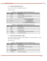
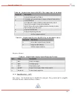
Page 11: ...tire message must be less than the MTU size The connected unit may display the ASCII text as it sees fit or may discard the information Table 3 TXT Response Format Byte Value Type Description 1 0x01 Start of message 2 0x00 TXT Response ID 3 N Number of text bytes to follow 4 to N 3 ASCII chars ASCII text Null termination not required N 4 checksum Frame check sequence See paragraph 2 1 Table 4 Exam...

Page 12: ...iption 1 0x01 Start of message 2 0x03 NAK Response ID 3 0x02 NAK responses always have 2 parameter bytes 4 5 Command ID ID of command that is being NAK d Command IDs are 8 bits in commands but are extended to 16 bits in an NAK 6 checksum Frame check sequence See paragraph 2 1 2 3 4 ERR Response The ERR response is generated when a command is not recognized or when an error occurs during the proces...

Page 13: ...ways have 2 parameter bytes 4 5 Unsigned integer Value 6 checksum Frame check sequence See paragraph 2 1 2 3 6 CMD Response The command response is generated by any command that requires a response that does not fit any of the prior response types The content of the response is dependent on the command and the nature of the response Table 10 CMD Response Format Byte Value Type Description 1 0x01 S...

Page 14: ...nds will return a VALUE response or a response having the same message ID as the command followed by and ACK 2 Data transfer activities have a unique message sequence that is dependent on whether an upload or download is requested the size of the transfer and any errors that may occur during transfer 2 6 CAMERA MEMORY DATA DOWNLOAD Information in non volatile memory may contain some information th...

Page 15: ...ransmission the CU may send a Data Transfer Upload Retry message 0x46 to indicate an error The retry contains one 16 bit parameter that is the packet number of the last packet received in order Upon receipt of this message the TIM will retransmit all packets following the packet number At any time the CU may send a Data Transfer Abort message 0x43 Upon receipt of this message the TIM will terminat...

Page 16: ...5 unsigned integer Packet number The first packet is 0 6 to N 3 any Packet payload The number of bytes in this array varies These are a portion of the bytes of the payload object being sent from the TIM N 4 Checksum Frame check sequence Response Format There is no response to this command unless packet is corrupted or is the last packet of the transfer If this packet is corrupted the CU should gen...

Page 17: ...47 Description Indicates the CU has received all packets of the download and data transfer operations will cease Command Format Table 15 Data Transfer Download Complete Command Format Byte Value Description 1 0x01 Start of message 2 0x47 Data Transfer Download Complete Command ID 3 0x00 Parameters length 4 Checksum Frame check sequence Response Format There is no response to this command Upon rece...

Page 18: ...ial command to the camera 0x01 0x73 0x0a 0x00 0x00 0x00 0x01 0x00 0x01 0x00 0x1a 0x00 0x00 0x66 Table 18 TIM Manufacturing Information Item Length in bytes Conversion from raw bytes Mfg date information 2 Year int data 0 256 int data 1 Mfg date information 1 Month int data 2 Mfg date information 1 Day int data 3 Mfg date information 2 Year int data 4 256 int data 5 Mfg date information 1 Month int...

Page 19: ...ze and CRC of the upload see Figure 2 Figure 2 Upload to TIM Message Sequence Diagram The TIM checks the size and region parameters and if acceptable responds with an ACK and setup response The setup response message has the same command ID as the setup message 0x74 and has 3 16 bit parameters The CU then begins sending packets to the TIM using Data Transfer Upload Packet messages 0x72 Each packet...

Page 20: ...e flash is being programmed followed by a flow control message with ID 10 to indicate that the upload has been successful the flash burn is complete data transfer operations will now cease 2 7 1 Data Transfer Upload Setup 0x74 This message is used as both a command to the TIM and a response to the CU Description Sets up a transfer from the connected unit to the TIM Command Format Table 19 Data Tra...

Page 21: ...response provides flow control and error notification to CU Command Format As a command this message carries payload data for a data transfer upload to the TIM from the CU The message contains a 16 bit unsigned zero based packet number followed by payload bytes Following the payload bytes is a 16 bit packet CRC The number of payload bytes will vary but the entire message must be less than the MTU ...

Page 22: ...e message 4 Upload complete Flash operations underway CU should cease transmission of packets until follow up message is received 5 Transfer CRC error CU should cease data transfer operations 6 Data length error CU should cease data transfer operations 8 Flash sector programming underway CU should stop transmitting packets and wait for follow up messages 9 Flash sector programming complete CU shou...

Page 23: ...at Byte Value Description 1 0x01 Start of message 2 0x07 System Version Get Command ID 3 0x00 Parameters length 4 checksum Frame check sequence Response Format The TIM will respond with one or more TXT messages Each TXT message shall contain a null terminated string of less than 40 characters The number of messages and their contents are system specific As an example below are the version strings ...

Page 24: ...ength 4 to N 3 Zero terminated text string Length varies Note trailing null is included in parameters length N 4 checksum Frame check sequence Table 27 System Version Get TXT Response Format Multiple Responses Verbose Mode Enabled Export Control 9 Hz Frame Rate Limited Mode Byte Value Description 1 0x01 Start of message 2 0x00 TXT Response 3 N Parameters length 4 to N 3 Zero terminated text string...

Page 25: ...ith the Customer Non Volatile Read Command Command Format Table 29 Customer Non Volatile Read Command Format Byte Value Description 1 0x01 Start of message 2 0xCA Customer Non Volatile Read Command ID 3 0x00 Parameters length 4 checksum Frame check sequence Response Format Table 30 Customer Non Volatile Read Response Format Byte Value Description 1 0x01 Start of message 2 0x02 ACK Response 3 NN Pa...

Page 26: ...m Frame check sequence Response Format Table 32 Customer Non Volatile Write Response Format Byte Value Description 1 0x01 Start of message 2 0x02 ACK Response 3 0x02 Parameters length 4 5 0x0027 Customer Non Volatile Write Command ID 6 checksum Frame check sequence 3 1 4 Enable Colorization Command 0xCC Camera RTL Rel version 01 00 3532 or newer is required together with compatible CPU Rel version...

Page 27: ...e 3 0x02 Parameters length 4 5 0x00CC Colorization Enable Command ID 6 checksum Frame check sequence 3 1 5 8 Bit Colorization Selection Command 0xCD Camera RTL Rel version 01 00 3532 or newer is required together with compatible CPU Rel version Description Allows the user to select the one of 12 different 8 bit colorization selections Colorization must be enabled and the output video mode must be ...

Page 28: ... possible colorization pallets 0 White Hot 1 Black Hot 2 Red Light 3 Arcus 4 Inferno 5 SoftLight 6 Sunset 7 Memoriam 8 Flamma Arcticus 9 Ocean 10 Rain 11 Factory Default 6 checksum Frame check sequence Response Format Table 36 8 Bit Colorization Selection Response Format Byte Value Description 1 0x01 Start of message 2 0x02 ACK Response 3 0x02 Parameters length 4 5 0x00CD 8 Bit Colorization Select...

Page 29: ... Orientation Select Response Format Byte Value Description 1 0x01 Start of message 2 0x02 ACK Response 3 0x02 Parameters length 4 5 0x00CF Video Orientation Source Select Command ID 6 Checksum Frame check sequence 3 1 7 Digital Video Source Select 0xD7 Description Control the digital video output multiplexer The camera default is to use the output of the Symbology module Command Format Table 39 Di...

Page 30: ...put of AGC Module 9 Output of Symbology Module All other values reserved Table 41 Digital Video Source IDs RTL Rel 01 00 0080 or prior Source ID Description 4 14 bit data output of zoom module 5 Output of AGC Module All other values reserved Response Format Table 42 Digital Video Source Select Response Format Byte Value Description 1 0x01 Start of message 2 0x02 ACK Response 3 0x02 Parameters leng...

Page 31: ...baud rate Note the baud rate for the USB port is fixed at 921600 Command Format Table 43 Baud Rate Set Command Format Byte Value Description 1 0x01 Start of message 2 0xF1 Baud Rate Set Command ID 3 0x02 Parameters length 4 5 Unsigned integer See table below Baud rate ID value 6 checksum Frame check sequence Table 44 Baud Rate ID Values Baud Rate ID Baud Rate Baud Rate ID Baud Rate 0 230400 8 7680...

Page 32: ...0 Parameters length Bit 7 Bit 6 Bit 5 Bit 4 Bit 3 Bit 2 Bit 1 Bit 0 4 deprecated deprecated EXTVID 0 in 1 out 2 off CAL 0 none 1 2 pt cold 2 2 pt hot 3 1 pt 4 1 pt no shutter 5 AGC 0 off 1 log equal auto 2 manual 3 linear equal deprecated Always reads 3 SHUTTE R 0 closed 1 open deprec ated deprec ated POL 0 blk 1 wht 6 deprecated Always reads 0x0 deprecated 7 Unsigned integer Deprecated 8 9 Unsign...

Page 33: ...pened to resume operations The 1 point no shutter field calibration allows the camera to compute NUC offsets that compensate for lens non uniformities When this operation is performed the camera should be pointed at a black body or suitable substitute that is at uniform temperature The shutter is not operated during this operation and should be open prior to initiation 3 2 1 Field Calibrate 0x27 D...

Page 34: ...e TIM shutter When the shutter is disabled it is forced closed and the shutter will ignore requests to open for field calibrations When the shutter is enabled it will open and respond to requests to open or close Command Format Table 51 Field Calibrate Shutter Disable Set Command Format Byte Value Description 1 0x01 Start of message 2 0x81 Field Calibrate Shutter Disable Set Command ID 3 0x02 Para...

Page 35: ...es will depend on current range and next range These field calibrations are required to maintain usable video The default is to have automatic calibration turned on Command Format Table 53 Automatic Calibration Toggle Command Format Byte Value Description 1 0x01 Start of message 2 0xAC Automatic calibration toggle command ID 3 0x00 Parameters length 4 checksum Frame check sequence Table 54 Automat...

Page 36: ...ations is five minutes Command Format Table 56 Automatic Calibration Period Set Command Format Byte Value Description 1 0x01 Start of message 2 0x12 Automatic calibration period set command ID 3 0x02 Parameters length 4 5 Unsigned integer Automatic calibration period in minutes 6 checksum Frame check sequence Response Format Table 57 Automatic Calibration Period Set Response Format Byte Value Desc...

Page 37: ...essage content example Example AUTOCAL Interval 300 sec Note trailing null is included in parameters length N 4 checksum Frame check sequence Table 60 Automatic Calibration Period Get ACK Response Format Byte Value Description 1 0x01 Start of message 2 0x02 ACK Response 3 0x02 Parameters length 4 5 0x0013 AutoCal Period Get Command ID 6 checksum Frame check sequence 3 2 6 Automatic Calibration Act...

Page 38: ...scription 1 0x01 Start of message 2 0x02 ACK Response 3 0x02 Parameters length 4 5 0x0026 AutoCal Activity Control Command ID 6 checksum Frame check sequence 3 2 7 Automatic Calibration Pending Activity Query 0x25 Description This command queries the camera for pending Automatic Calibration activities and specifies the type of AutoCal that is pending A suggested interval for checking for pending c...

Page 39: ... exclusive The AGC module converts 14 bit video data to 8 bit data The AGC has several operating modes that control how this conversion takes place Generally a histogram of the input data is computed upper and lower limits of useful video data are extracted black limit and white limit and a contrast stretch between those levels is performed Two histogram equalization modes are supported AGC freeze...

Page 40: ...essage 2 0x22 ICE Mode Min Max Command ID 3 0x02 Parameters length 4 5 0x0000 or 0x0001 0 preset value for low strength 1 preset value for high strength Table 67 ICE Mode Min Max Response Format Byte Value Description 1 0x01 Start of message 2 0x02 ACK Response 3 0x02 Parameters length 4 5 0x0022 ICE Mode Min Max Command ID 6 checksum Frame check sequence 3 3 2 ICE Mode Enable Command 0x23 Camera ...

Page 41: ...trength from 0 7 in 1 unit increments The lowest setting is 0 the highest setting is 7 Recommend using lower values when looking at lower contrast scenes and higher values when looking at dynamic scenes Command Format Table 70 ICE Mode Strength Command Format 2 0x1E ICE Mode Strength Command ID 3 0x02 Parameters length 4 5 0x0000 0x0007 ICE Strength value 6 checksum Frame check sequence Response F...

Page 42: ...23 ICE high frequency threshold value 6 checksum Frame check sequence Response Format Table 73 ICE Mode High Frequency Threshold Response Format Byte Value Description 1 0x01 Start of message 2 0x02 ACK Response 3 0x02 Parameters length 4 5 0x001F ICE Mode High Frequency Threshold Command ID 6 checksum Frame check sequence 3 3 5 AGC Mode Set 0x2A Description Sets the operating mode for Automatic G...

Page 43: ...age 2 0x02 ACK Response 3 0x02 Parameters length 4 5 0x002A AGC Mode Set Command ID 6 checksum Frame check sequence 3 3 6 AGC Black Hot Polarity Set 0x28 Description Commands the system to display hotter objects in the image as darker blacker and cooler objects as lighter The default camera setting is white hot Command Format Table 77 AGC Black Hot Polarity Set Command Format Byte Value Descriptio...

Page 44: ...et Command Format Byte Value Description 1 0x01 Start of message 2 0x29 AGC White Hot Polarity Set Command ID 3 0x00 Parameters length 4 checksum Frame check sequence Response Format Table 80 AGC White Hot Polarity Set Response Format Byte Value Description 1 0x01 Start of message 2 0x02 ACK Response 3 0x02 Parameters length 4 5 0x0029 AGC White Hot Polarity Set Command ID 6 checksum Frame check s...

Page 45: ...in gain 256 6 checksum Frame check sequence Response Format Table 82 AGC Manual Gain Set Response Format Byte Value Description 1 0x01 Start of message 2 0x02 ACK Response 3 0x02 Parameters length 4 5 0x0032 AGC Manual Gain Set Command ID 6 checksum Frame check sequence 3 3 9 AGC Manual Level Set 0x33 Description Sets level value used by AGC when configured to Manual Mode NOTE This command has no ...

Page 46: ...4 AGC Manual Level Set Response Format Byte Value Description 1 0x01 Start of message 2 0x02 ACK Response 3 0x02 Parameters length 4 5 0x0033 AGC Manual Level Set Command ID 6 checksum Frame check sequence 3 3 10 AGC Gain Bias Set 0x82 Description Sets gain bias value Gain bias is similar to a contrast control Command Format Table 85 AGC Gain Bias Set Command Format Byte Value Description 1 0x01 S...

Page 47: ... is a two piece formula For gain_bias 2047 gain_factor 0 75 gain_bias 2047 0 25 For gain_bias 2048 gain_factor 3 gain_bias 2048 2047 1 Figure 4 Gain Factor Curve 3 3 11 AGC Level Bias Set 0x83 Description Sets level bias value Level bias is similar to a brightness control 0 0000 0 2500 0 5000 0 7500 1 0000 1 2500 1 5000 1 7500 2 0000 2 2500 2 5000 2 7500 3 0000 3 2500 3 5000 3 7500 4 0000 0 256 51...

Page 48: ... 4095 0x0FFF maximum level bias gain factor 255 6 checksum Frame check sequence For level bias 2047 level _factor 255 level_bias 2047 255 For level bias 2048 level factor 255 level_bias 2047 2048 Figure 5 Level Bias Chart Response Format Table 88 AGC Level Bias Set Response Format Byte Value Description 1 0x01 Start of message 2 0x02 ACK Response 256 000 192 000 128 000 64 000 0 000 64 000 128 000...

Page 49: ... noise but will reduce sensitivity in low contrast scenes The AGC Gain Limit Noise Reduction Mode which is an NV parameter works to limit the pixel to pixel difference and thus reducing the effects of noise across the entire scene This limit has the effect of smoothing out the image and hence the AGC provides a better overall image It is possible but not recommended to enable both the AGC Gain Lim...

Page 50: ...xD2 Description Sets the gain limit offset for AGC histogram processing The default value is 1 NOTE This command has no effect if ICE is enabled Command Format Table 91 AGC Gain Flatten Offset Set Command Format Byte Value Description 1 0x01 Start of message 2 0xD2 AGC Gain Flatten Offset Set Command ID 3 0x02 Parameters length 4 5 unsigned integer 0 to 65535 AGC gain flatten offset value 6 checks...

Page 51: ...and Format Table 93 AGC Region of Interest Sub Command Table ID Description Additional Parameters Response 0 Get ROI None Text String ACK 1 Get ROI Limit None Text String ACK 2 Set ROI 4 unsigned integer ACK 3 Burn ROI to NV Param None ACK All other values reserved Command Format sub command 0x0000 Get Table 94 AGC ROI Get Command Format Byte Value Description 1 0x01 Start of message 2 0x84 AGC RO...

Page 52: ...x0001 Get Limit Table 97 AGC ROI Get Limit Command Format Byte Value Description 1 0x01 Start of message 2 0x84 AGC ROI Get Limit Command ID 3 0x02 Parameters length 4 5 0x0001 Sub command Get Internal ROI Limit 6 checksum Frame check sequence Response Format Table 98 AGC ROI Get Limit Response 1 Format Byte Value Description 1 0x01 Start of message 2 0x00 Text message 3 0x39 Parameters length 4 5...

Page 53: ...t 10 11 Unsigned integer XSTOP within valid limits see Get Limit 12 13 Unsigned integer YSTOP within valid limits see Get Limit 14 checksum Frame check sequence Response Format Table 101 AGC ROI Set Command ACK Response Format Byte Value Description 1 0x01 Start of message 2 0x02 ACK Response 3 0x02 Parameters length 4 5 0x84 AGC ROI Set Command ID 6 checksum Frame check sequence Command Format su...

Page 54: ...OTE This command has no effect if ICE is enabled Command Format Table 104 AGC Options Set Command Format Byte Value Description 1 0x01 Start of message 2 0xA0 AGC Options Set Command ID 3 0x02 Parameters length 4 5 0x000A AGC gain flatten offset value 6 7 unsigned integer 0 to 65535 Pixel sum upper bound 8 9 unsigned integer 0 to 65535 Pixel sum lower bound 10 checksum Frame check sequence Respons...

Page 55: ...et Command ID 3 0x02 Parameters length 4 5 Unsigned integer See table below Zoom magnification ID value 6 checksum Frame check sequence Table 107 Zoom Magnification ID Values Zoom Magnification ID Zoom 0 1 00 7 2 75 1 1 25 8 3 00 2 1 50 9 3 25 3 1 75 10 3 50 4 2 00 11 3 75 5 2 25 12 4 00 6 2 50 Response Format Table 108 Zoom Magnification Set Response Format Byte Value Description 1 0x01 Start of ...

Page 56: ... of FPA center 6 7 Signed integer Vertical offset from the center Negative values center the zoom above the FPA center Positive values center the zoom below the FPA center 8 checksum Frame check sequence Response Format Table 110 Zoom Pan Set Response Format Byte Value Description 1 0x01 Start of message 2 0x02 ACK Response 3 0x02 Parameters length 4 5 0x00A5 Zoom Pan Set Command ID 6 checksum Fra...

Page 57: ...checksum Frame check sequence Response Format Table 112 Zoom Store Current Settings Response Format Byte Value Description 1 0x01 Start of message 2 0x02 ACK Response 3 0x02 Parameters length 4 5 0x00A6 Zoom Pan Set Command ID 6 checksum Frame check sequence ...

Page 58: ...tion the most recent will be used 5 Parallel Digital Video Output Enable Boolean 0 disable non zero enable 1 The Parallel digital output and the RS170 share pins If both are enabled on power up RS170 will be output If both are enabled during operation the most recent will be used 6 Camera Link Output Enable Boolean 0 disable non zero enable 1 7 Video Output Mux Select Unsigned integer 0 Output of ...

Page 59: ... 0 to 65535 3 11 AGC Upper Lower Bounds Percent Unsigned integer 0 to 100 1 14 Automatic Field Calibration Interval Unsigned integer 1 to 65535 minutes 5 Interval between automatic field calibrations Setting this value to 0 will disable time based automatic calibrations not all calibrations will be disabled This value must be greater than the minimum Autocal interval 16 Frame Rate Unsigned integer...

Page 60: ...GC Gain Limit Noise Reduction Mode Unsigned fixed point integer 0x0010 Enable 0x0FFF Disable 0x0010 Controls the AGC Noise Reduction Gain Factor Set to 0x0FFF to disable noise reduction mode 38 AGC Black Hot Enable at Power Up Boolean 0 Disable 1 Enable 0 Value is applied only at the time of power up 39 AGC Auto Mode Gain Bias at Power Up Unsigned integer 0 4096 2047 Value is applied only at the t...

Page 61: ...equired together with compatible CPU Rel version 47 ICE Mode Enable Boolean 0 Disable 1 Enable 0 Value is applied only at the time of power up Camera RTL Rel version 01 00 3532 or newer is required together with compatible CPU Rel version 48 Frame Buffer Video Suspend Action Unsigned integer 0 freeze video 1 output gray value 0 What happens to the video when a 1 point event happens Camera RTL Rel ...

Page 62: ...00 3532 or newer is required together with compatible CPU Rel version 54 Symbology Enable DRS Logo Boolean 0 Disable 1 Enable 0 NVParam 52 must also be enabled Camera RTL Rel version 01 00 3532 or newer is required together with compatible CPU Rel version 55 Symbology Polarity Enable Boolean 0 Disable 1 Enable 0 NVParam 52 must also be enabled Camera RTL Rel version 01 00 3532 or newer is required...

Page 63: ...ompatible CPU Rel version 64 Lens Calibration Table Selection Unsigned integer Table 1 0x0000 Table 2 0x0001 Table 3 0x0002 Table 4 0x0003 Table 5 0x0004 0 Not Valid unless the lens calibration is enabled Camera RTL Rel version 01 00 0080 or newer is required together with compatible CPU Rel version 65 ICE Mode Min Max On Boolean 0 preset value for low strength 1 preset value for high strength 0 I...

Page 64: ... the left of FPA center Positive values center the zoom to the right of FPA center Range depends on power on zoom magnification Values out of range will be clipped at maximum 0 Camera RTL Rel version 01 00 3532 or newer is required together with compatible CPU Rel version 69 Zoom Vertical Offset Power On Value Signed Integer Vertical offset from the center Negative values center the zoom above the...

Page 65: ...2 160 Values outside of allowable range will be truncated to nearest legal value Camera RTL Rel version 01 00 3995 or newer is required together with compatible CPU Rel version 75 Crosshairs Y Location Unsigned integer 6 to 232 120 Values outside of allowable range will be truncated to nearest legal value Camera RTL Rel version 01 00 3995 or newer is required together with compatible CPU Rel versi...

Page 66: ...3 5 1 Non Volatile Parameters Default Set 0xB3 Description Load the default non volatile parameters Please note 1 This command causes one or more sectors of flash memory on the TIM to be erased and reprogrammed See general notes on command timing 2 If flash is successfully reprogrammed this command results in an ACK message 3 If flash programming fails this command results in an ERR response conta...

Page 67: ...mat Table 116 Non Volatile Parameters Get Command Format Byte Value Description 1 0x01 Start of message 2 0xB5 Non volatile parameters get command ID 3 0x02 Parameters length 4 5 Unsigned integer Non volatile parameter ID 6 checksum Frame check sequence Response Format This command generates two response messages The first is a VALUE message that contains the value of the non volatile parameter Th...

Page 68: ...general notes on command timing 2 If flash is successfully reprogrammed this command results in an ACK message 3 If flash programming fails this command results in an ERR response containing an informative string Command Format Table 119 Non Volatile Parameters Set Command Format Byte Value Description 1 0x01 Start of message 2 0xB0 Non volatile parameters set command ID 3 0x04 Parameters length 4...

Page 69: ...sting of a row and column index Row index 0 is the upper row of the FPA The row index must be less than height of the FPA in pixels If the row index is out of range the command will result in an error message Column index 0 is the left most column of the FPA The column index must be less than the width of the FPA If the column index is out of range the command will result in an error message The c...

Page 70: ...xel cursor Command Format Table 123 Defective Pixel Map Cursor Position Set Command Format Byte Value Description 1 0x01 Start of message 2 0x3A Defective Pixel Map Cursor Position Set 3 0x04 Parameters length 4 5 unsigned integer 0 to FPA rows 1 Cursor row index Valid values are 0 to 239 6 7 unsigned integer 0 to FPA cols 1 Cursor column index Valid values are 0 to 319 8 checksum Frame check sequ...

Page 71: ...uence Response Format Table 126 Defective Pixel Map Cursor Value Set Response Format Byte Value Description 1 0x01 Start of message 2 0x02 ACK response 3 0x02 Parameters length 4 5 0x0037 Defective Pixel Map Cursor Value Set Command ID 6 checksum Frame check sequence 3 6 4 Defective Pixel Map Pixel Add 0x3B Description Add a single pixel to the defective pixel map Command Format Table 127 Defectiv...

Page 72: ...the defect map All pixels on the row will be marked as defective Command Format Table 129 Defective Pixel Map Row Add Command Format Byte Value Description 1 0x01 Start of message 2 0x34 Defective Pixel Map Row Add Command ID 3 0x02 Parameters length 4 5 unsigned integer 0 to FPA rows 1 Cursor row index Valid values are 0 to 239 6 checksum Frame check sequence Response Format Table 130 Defective P...

Page 73: ...t Table 132 Defective Pixel Map Column Add Response Format Byte Value Description 1 0x01 Start of message 2 0x02 ACK Response 3 0x02 Parameters length 4 5 0x0036 Defective Pixel Map Column Add Command ID 6 checksum Frame check sequence 3 6 7 Defective Pixel Map Remove Item 0x35 Description Removes a dead pixel row or column from the defective pixel map Command Format Table 133 Defective Pixel Map ...

Page 74: ...emoved from the defect map 1 Remove row All pixels at row index will be removed from the defect map The column index is ignored for this operation 2 Remove column All pixels at the column index will be removed from the defect map The row index is ignored for this operation 3 6 8 Defective Pixel Map Remove All 0x3C Description Remove all pixels from the defective pixel map Command Format Table 136 ...

Page 75: ... 1 0x01 Start of message 2 0xFB Defective Pixel Map Flash Burn Command ID 3 0x04 Parameters length 4 5 0xXX Defective Pixel Map Flash Sector 6 7 0x00 Write 8 checksum Frame check sequence Response Format Table 139 Defective Pixel Map Flash Burn Response Format Byte Value Description 1 0x01 Start of message 2 0x02 ACK Response 3 0x02 Parameters length 4 5 0x00FB Defective Pixel Map Remove All Comma...

Page 76: ...equence Response Format This command results in two response messages The first response message is a TXT message containing the echoed string The second response message is an ACK message Table 141 Serial Echo TXT Response Format Byte Value Description 1 0x01 Start of message 2 0x06 Echo command 3 N Parameters length 4 to N 3 Null terminated string Echoed string N 4 checksum Frame check sequence ...

Page 77: ...2 ACK Response 3 0x02 Parameters length 4 5 0x0018 Tcomp Disable Command ID 6 checksum Frame check sequence 3 7 3 Test Pattern Select 0xF4 Description Enables and selects a video test pattern Selecting test pattern 0x0000 disables the test pattern generator This test pattern replaces the input video stream from the FPA and facilitates testing of downstream processing blocks This requires a sequenc...

Page 78: ... Start of message 2 0xF4 Test Pattern Select Command ID 3 0x02 Parameters length 4 5 unsigned integer See table below Test Pattern ID 6 checksum Frame check sequence Table 146 Test Pattern IDs Test Pattern ID Description Test Pattern ID Description Test Pattern ID Description 0x0000 Off 0x8003 Horizontal Bars 0x8007 Gray 0x8000 Horizontal Ramp 0x8004 Vertical Bars 0x8008 NUC 14 bit 0x8001 Vertical...

Page 79: ...ength 4 5 Unsigned integer 0 disables RS170 test pattern non zero enables RS170 test pattern 6 checksum Frame check sequence Response Format Table 149 RS170 Test Pattern Enable Response Format Byte Value Description 1 0x01 Start of message 2 0x02 ACK Response 3 0x02 Parameters length 4 5 0x00D8 RS170 Test Pattern Enable Command ID 6 checksum Frame check sequence 3 7 5 Verbose Mode Toggle 0xFF This...

Page 80: ...ommand ID 3 0x02 Parameters length 4 5 0x0000 0x0001 0 disables verbose mode 1 enables verbose mode 6 checksum Frame check sequence Response Format Table 152 Verbose Mode Toggle Response Format Byte Value Description 1 0x01 Start of message 2 0x02 ACK Response 3 0x02 Parameters length 4 5 0x00FF Verbose Mode Toggle Command ID 6 checksum Frame check sequence ...

Page 81: ...er Deprecated 0x22 ICE Mode Min Max 01 00 3532 or newer Deprecated 0x23 ICE Mode Enable 01 00 3532 or newer 0x25 AutoCal Pending Activity Query 0x26 AutoCal Activity Control Enable Disable 0x27 Field Calibrate 0x28 AGC Black Hot Enable 0x29 AGC White Hot Enable 0x2A AGC Mode Set 0x32 AGC Manual Gain Set 0x33 AGC Manual Level Set 0x34 Defective Pixel Map Row Add 01 00 0080 or newer 0x35 Defective P...

Page 82: ...ter Disable 0x82 AGC Gain Bias Set 0x83 AGC Level Bias Set 0x84 AGC Region of Interest 0xA0 AGC Options Set 0xA4 Zoom Magnification Set 0xA5 Zoom Pan Set 0xA6 Zoom Store Current Settings 01 00 3532 or newer 0xAC Automatic Calibration Toggle 0xB0 Non Volatile Parameters Set 0xB3 Non Volatile Parameters Set Default 0xB5 Non Volatile Parameters Get 0xCA Customer Non Volatile Read 01 00 0080 or newer ...

Page 83: ...quired needs to be paired with compatible CPU Rel version 0xD7 Digital Video Source Select 0xD8 RS170 Test Pattern Enable 0xF1 Baud Rate Set 0xF2 System Status Get 0xF4 Test Pattern Select 0xFB Defective Pixel Map Flash Burn 01 00 0080 or newer 0xFF Verbose Mode Toggle ...

Reviews: