background image

SECTION 2 

LEARNING ABOUT YOUR ARMOR X7


 PAGE 36 


9711-26400-0001 

EXPORT CONTROLLED – SEE PAGE 3 

Rev A 

R ear P anel F eatures  

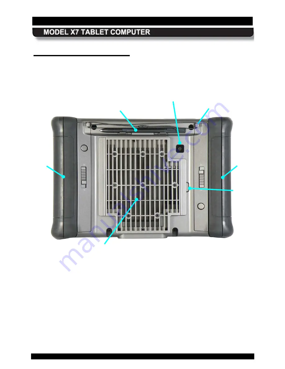
The rear panel of the X7 houses a built-in webcam, a cooling register, two battery bays and a 
removable cooling register/cover  that provides access to installed radio modules, a SIM card 
socket, and a micro SD socket. A slot for the active pen is built into the back panel with posts to 
secure the lanyard. 


Figure 4.  Key Features - Rear Panel 


HEAT SHIELD AND COOLING 

REGISTER 

BATTERY  

#2 

BATTERY  

#1 

WEBCAM 

ACTIVE 

PEN WITH LANYARD 

LANYARD 
POST (X2) 

COVER  

REMOVAL  

SLOT 

Summary of Contents for ARMOR X7

Page 1: ...USER S GUIDE REVISION A MODEL X7 TABLET COMPUTER Copyright 2010 2011 DRS Tactical Systems Inc Melbourne Florida All Rights Reserved Go to Table of Contents...

Page 2: ...26400 0001 EXPORT CONTROLLED SEE PAGE 3 Rev A To learn more about ARMOR accessories please call 1 888 872 1100 VEHICLE DOCK DESK DOCK BATTERY CHARGER SOLID STATE DRIVE MINI USB ADAPTER BREAKOUT BOX S...

Page 3: ...pment does cause harmful interference to radio or television reception which can be determined by turning the equipment off and on the user is encouraged to try to correct the interference by one or m...

Page 4: ...um shielding Equipment or its transmit antenna that is installed outdoors is subject to licensing Op ration dans la bande 2 4 GHz Pour emp cher que cet appareil cause du brouillage au service faisant...

Page 5: ...IT LV LT LU MT NL NO PL PT RO SK SI ES SE CH LE UK HR MK TR Frequency band 5150 5350 MHz restricted to indoor use FR 2400 2483 5 MHz frequency band restricted to indoor use IT For private use a genera...

Page 6: ...FRONT MATTER PAGE 6 9711 26400 0001 EXPORT CONTROLLED SEE PAGE 3 Rev A...

Page 7: ...otice Please contact DRS Technical Support for information concerning updates to this document This publication and any accompanying software may not in whole or in part be copied photocopied translat...

Page 8: ...FRONT MATTER PAGE 8 9711 26400 0001 EXPORT CONTROLLED SEE PAGE 3 Rev A This Page Intentionally Left Blank...

Page 9: ...PLOSION HAZARD DO NOT DISCONNECT WHILE CIRCUIT IS LIVE UNLESS AREA IS KNOWN TO BE NON HAZARDOUS AVERTISSEMENT RISQUE D EXPLOSION NE PAS D BRANCHER TANT QUE LE CIRCUIT EST SOUS TENSION MOINS QU IL NE S...

Page 10: ...rial that is hazardous to your health If battery contents come in contact with the eyes IMMEDIATELY flush the affected area with clean water for 15 minutes and have someone else summon medical attenti...

Page 11: ...vehicles that can supply a regulated 10VDC to 30 VDC nominal 19 VDC Voltages outside this range could cause damage to the computer CAUTION DO NOT connect the computer to more than one power source at...

Page 12: ...AINSI CLASS ES IMPROPRES SA COTE DE S CURIT CAUTION When using IEEE 802 11a wireless LAN in Canada this product is restricted to indoor use due to its operation in the 5 15 to 5 25 GHz frequency rang...

Page 13: ...anel Features 30 Display 31 Controls 31 Indicator Panel 34 Speaker 35 Noise Cancelling Stereo Microphones 35 Rear Panel Features 36 Cooling Register 37 Battery Bays 37 Webcam 37 Bottom Panel Features...

Page 14: ...utting the Computer into Hibernate Mode 63 Indicator State Summary 64 Configuring and Controlling your Wireless Radios 66 Installing a Micro SD SDHC Card 66 Installing the Optional D Rings 66 Configur...

Page 15: ...nal GPS Receiver 96 The u center GPS Application Window 97 u center User s Guide 97 Assisted GPS 97 Enabling and Disabling Your Wireless Radios 99 Wireless Signal Quality 101 Using your Radios with an...

Page 16: ...4 TS 03 Tablet will not boot into Windows 155 TS 04 Tablet will not recognize a battery 156 TS 05 Tablet is locked up 157 TS 06 Cannot connect to wireless network 158 7 MAINTAINING YOUR AR MOR X7 161...

Page 17: ...Batteries 190 Avoiding Overly Discharging Your Batteries 191 What to Do for an Overly Discharged Battery 191 How to Charge Your Batteries 192 Charging Times 192 Charging Temperatures 192 Setting the C...

Page 18: ...a Battery 204 Your Battery s Warranty 205 Where to Purchase Replacement Batteries 205 How to Store Batteries When Not in Use 205 Short Term Storage 205 Long Term Storage 205 Battery Tips for Best Perf...

Page 19: ...RT CONTROLLED SEE PAGE 3 Rev A Explanation of Active Pen Side Button Options 217 APPE NDIX B 219 Using the X7 External Battery Charger 219 Charger LED Status Indications 220 APPE NDIX C 221 Sierra One...

Page 20: ...igure 18 X7 RF Vehicle Dock 48 Figure 19 Examples of X7 Vehicle Dock Mounting Solutions 49 Figure 20 X7 Breakout Box 49 Figure 21 Industrial Vehicle Surge Suppressor 50 Figure 22 X7 Vehicle Power Supp...

Page 21: ...s Main Screen with Options Disabled 115 Figure 59 ARMORutils Battery Monitor Dialog 116 Figure 60 ARMORutils Battery Information Window 117 Figure 61 ARMORutils Charger Control Settings Window 118 Fig...

Page 22: ...tion 171 Figure 95 System Settings Power Button Options 176 Figure 96 Diagnostics Event Recorder Window 178 Figure 97 Armor Utilities Screen Backlight Tab 182 Figure 98 Intel Graphics Screen Rotation...

Page 23: ...e 16 Configuring the Sierra OneClick Application to Use NDIS 95 Table 17 Configuring the u Center Com Port 96 Table 18 Obtaining the AGPS Password from u blox 98 Table 19 Enabling and Disabling Your W...

Page 24: ...FRONT MATTER PAGE 24 9711 26400 0001 EXPORT CONTROLLED SEE PAGE 3 Rev A This Page Intentionally Left Blank...

Page 25: ...solution LCD display that is readable even in bright sunlight In addition you now have both a touch screen and an active pen screen at your fingertips The X7 batteries are hot swappable which means yo...

Page 26: ...own below Please verify that all of these items are present and in good condition Contact your ARMOR X7 computer sales representative if any item is missing or damaged Contact your ARMOR sales represe...

Page 27: ...the guide in your Adobe PDF Reader The latest version of Adobe PDF Reader is available for downloading free from www adobe com While viewing this guide you can click on any Figure or Table reference...

Page 28: ...SECTION 1 WELCOME AND INTRODUCTION PAGE 28 9711 26400 0001 EXPORT CONTROLLED SEE PAGE 3 Rev A This Page Intentionally Left Blank...

Page 29: ...full 8 hour shift operating on one set of batteries Its hot swap battery access means you can change a battery at any time without the need for tools and without having to power down the tablet Innov...

Page 30: ...res NOTE All references to front back top bottom and left right are relative to the face on view as shown in Figure 1 Figure 1 ARMOR X7 Key Features Front View FINGERPRINT SENSOR HIGH BRIGHTNESS DUAL...

Page 31: ...de even more precision with the touch screen You can choose to operate with both screens Dual Mode or with only one screen Touch Only or Pen Only Both screens have the same clear crisp viewing quality...

Page 32: ...ftware for instructions on how to setup and use the FPS F n F unc tion B utton This button is used with PBs P1 P2 and P3 button combos to activate three additional functions Press and release the Fn b...

Page 33: ...the Windows desktop The computer will perform a normal shutdown Computer powered on and awake Press and hold for 5 or more seconds emergency shutdown Computer shuts down immediately and does not save...

Page 34: ...Devic e Ac tivity Indic ator A blue LED that is on intermittently whenever a storage device is being accessed Storage devices include the embedded mSATA drive and an optional SD flash memory card and...

Page 35: ...ness will increase proportionally if the light level decreases the display and indicator brightness will decrease proportionally S peaker A single high volume speaker is located on the top left of the...

Page 36: ...er two battery bays and a removable cooling register cover that provides access to installed radio modules a SIM card socket and a micro SD socket A slot for the active pen is built into the back pane...

Page 37: ...access to the wireless radio cards a SIM card socket a micro SD socket and any optional or custom cards B attery B ays Your X7 is shipped with two custom designed batteries that are installed in bays...

Page 38: ...DC power input jack a mini USB connector and a 20 pin docking connector The docking connector contains two RF ports to connect the X7 to external GPS and wireless antennas Figure 7 Key Features Botto...

Page 39: ...on Figure 8 shows a single X7 battery Each battery has three locking slots that fit into three corresponding hooks on the battery latch A multi LED battery charge indicator or fuel gauge is located ne...

Page 40: ...he active pen P N 0000F50872 0000 that comes with your X7 Figure 9 has circuitry in the tip that interacts with the digitizer assembly built into the tablet display The digitizer detects the pen tip c...

Page 41: ...using this cloth with the X7 display Figure 11 ARMOR Microfiber Cleaning Cloth T hermal T rans fer P ads Two thermal transfer pads are included with your X7 in case the original pads are damaged while...

Page 42: ...he size of the SIM card compared to a quarter NOTE The SIM card shown is blank a valid card has the customer s account code printed on it You must have a SIM card installed in order to use your Gobi r...

Page 43: ...rnal F lexs pac e The internal flexspace accepts a custom circuit board or module that connects to the X7 using one of two different interface adapters mini PCIe or PCI USB The example in Figure 15 sh...

Page 44: ...re 15 X7 Internal Flexspace Figure 16 ARMOR X7 Battery Adapter Flexspace Concept For more information on the X7 s expansion capabilities contact DRS Tactical Systems Inc toll free at 1 800 872 1100 EX...

Page 45: ...blox G P S R eceiver C ard The u blox GPS receiver is capable of downloading position data from the GPS or Galileo satellite networks and enables you to pinpoint your position anywhere in the world t...

Page 46: ...D Rings The D Rings are constructed of super tough reinforced plastic that can support up to 43 pounds each With these D Rings you can attach your own carrying handle shoulder strap or other accessor...

Page 47: ...has connectors for 3 USB ports an RJ45 Ethernet port an RS 232 serial port and a DC power input jack The breakout box also has internal provisions for two GPIO ports The breakout box plugs into the do...

Page 48: ...n in Figure 18 This dock has two RF connectors that are used to connect external GPS and wireless antennas The top clamp mechanism that holds the X7 in place can withstand over 50 000 latch unlatch cy...

Page 49: ...B reakout B ox The X7 breakout box P N 9800F26600 0000 is used with both the desk dock and the vehicle dock When used with the desk dock it is plugged into a connector in the base of the desk dock an...

Page 50: ...is section DRS offers its Industrial Vehicle Surge Suppressor IVSS P N 9800F50856 0000 shown in Figure 21 We also offer an installation kit to connect your surge suppressor to your vehicle s battery s...

Page 51: ...llation includes a docking station breakout box 50 pin cable surge suppressor or power supply and mount of your choice A sample system is shown in Figure 23 external antennas and cables not shown Figu...

Page 52: ...backlighting with Automatic Light Sensor Integrated stylus holder Autosense dual mode digitizer 2540 dots inch 0 001mm resolution and resistive touch glass film glass 2048 dots resolution X Y 0 25 mm...

Page 53: ...with special adapter 2x USB 2 0 ports 2x bi directional GND Open discretes to EC processor 5V 1A 3 3V 1A power for active modules User accessible compartment under cooling register 1x mini PCIe port...

Page 54: ...rating Vibration Operating Composite Wheeled Vehicle Exposure Storage Composite Two Wheeled Trailer Exposure Shock Operating 30g 11ms half sine operational shock Storage 50 g s 11ms half sine Drop tes...

Page 55: ...crophone Input Touch Panel Controller Optically Bonded LCD Assy PCIe X1 Bluetooth USB Hub Battery Exp USB 0 USB 1 USB 2 USB 7 USB 9 Mini PCIe WLAN Mini PCIe GPS SATA 0 GPIO EXP Conn Button Board Backl...

Page 56: ...SECTION 2 LEARNING ABOUT YOUR ARMOR X7 PAGE 56 9711 26400 0001 EXPORT CONTROLLED SEE PAGE 3 Rev A This Page Intentionally Left Blank...

Page 57: ...ct only in vehicles with a regulated voltage supply of 10 to 30 VDC nominal 19VDC Voltages outside this range could cause unstable operation or result in permanent damage to the computer CAUTION Use o...

Page 58: ...puter as shown in Figure 25 The batteries are identical and can be installed in either bay Follow the procedure in Table 2 to install the batteries NOTE If you do not plan to use your computer right a...

Page 59: ...he batteries to charge until the Charge Fault indicator turns off This could take anywhere from 2 to 5 hours depending on the type of battery and the current level of charge of the batteries You can w...

Page 60: ...SECTION 3 GETTING STARTED PAGE 60 9711 26400 0001 EXPORT CONTROLLED SEE PAGE 3 Rev A Figure 26 X7 Battery FUEL GAUGE BUTTON FUEL GAUGE 1 2 3 4 5 BATTERY CONNECTOR...

Page 61: ...OBE setup procedure 2 On the left control panel press and hold the Power button for 1 2 seconds and then release When the computer boots up the Microsoft Out of Box Experience OOBE screen will open NO...

Page 62: ...ring the start up process All units are configured at the factory to automatically boot to the Microsoft Windows desktop unless a custom configuration has been requested Turning the C omputer Off Norm...

Page 63: ...d hold the Power button for 1 2 seconds and then release This will take you back to the desktop and you can resume your session where you left off Indications that your X7 is As leep In Sleep mode you...

Page 64: ...g intermittently On N A Installed The WLAN or WWAN radio is searching for a network connection or Bluetooth is transmitting data to a peripheral Off On N A Installed One or more installed radios exclu...

Page 65: ...dervoltage or overcurrent condition or battery failure NOTE The LED will turn off when the fault condition is removed Power blue On On N A Installed Computer is powered up Flashing 1 sec on 2 sec off...

Page 66: ...ver at the back of the computer For instructions on how to remove the rear cover and install the card refer to Installing a Micro SD or SDHC Card Ins talling the Optional D R ings Follow the procedure...

Page 67: ...TION CONDITION OR INDICATION 1 Double click on the orange speaker icon in the systray The Realtek HD Audio Manager window opens with the Speakers main tab top of page open and the Speaker Configuratio...

Page 68: ...NDITION OR INDICATION 1 Click on the Microphone main tab at the top of the page The Microphone main tab opens with the Microphone Effects sub tab displayed as shown in Figure 28 2 Set up and adjust yo...

Page 69: ...een The Screen Setup dialog opens as shown in Figure 29 Click on Touch Only to deactivate the pen screen or click on Pen Only to deactivate the touch screen The screen option that is enabled will appe...

Page 70: ...open ARMORutils and click on the Backlight Setup option in the ARMORutils Main dialog window This will open the Backlight Setup dialog window shown in Figure 30 Figure 30 ARMORutils Backlight Setup D...

Page 71: ...ghtness in two ways by using pre programmed buttons PBs P1 P2 and P3 or by using options and buttons in the Backlight Setup dialog Us ing P 1 P 2 and P 3 to Adjus t B rightnes s When you first receive...

Page 72: ...en activates a tip switch that opens a right click menu Us ing the Ac tive P en Table 8 lists mouse type objectives you can perform using the X7 pen with the pen screen NOTE This description assumes t...

Page 73: ...ound and clicking on one or more of the following utilities Pen Tablet Properties utility Pen and Touch utility Tablet PC Settings utility Refer to Windows Display Utilities for information about thes...

Page 74: ...ght a label or option Fill selection boxes Activate buttons Deselect highlighted objects or release multiple objects Tap once Tap outside the object s Start an application or open a folder Tap twice M...

Page 75: ...ve pen that came with your X7 to calibrate the touch screen since the digitizer will detect the active pen tip and not allow you to proceed You will need to calibrate the touch screen using a fingerti...

Page 76: ...s or the active pen as shown in Figure 31 When the edge is visible tap on it twice to fully open it on the desktop as shown in Figure 32 Figure 31 Location of the Input Panel Figure 32 Input Panel Key...

Page 77: ...tom of the options window to access a Windows help tutorial about opening and position the Input Panel Opening Input P anel with a G es ture You can also use a side to side gesture to open the input p...

Page 78: ...gerprints you will need to swipe in each time you restart the computer Us ing the F ingerprint S ens or To use the fingerprint sensor swipe your finger or thumb from side to side at medium speed acros...

Page 79: ...his user s guide Click on the in the upper right corner of the window to access the application s help resources for detailed descriptions and instructions Unins talling your F ingerprint S oftware Sh...

Page 80: ...MMENTS 1 Double click on the Picasa 3 icon on the desktop The Picasa application window will open as shown in Figure 34 2 Click on the Capture photos or video button in the options bar see Figure 34 A...

Page 81: ...s types of barcodes and incorporate them in to your documents We have included two simple applications to demonstrate the barcode scanning capabilities of the X7 NOTE Ensure that adequate light can re...

Page 82: ...ed 2 3 from the camera and hold it steady A tone will announce successful barcode capture and the barcode number will appear at the bottom of the window The captured barcode is stored in the Windows c...

Page 83: ...on window opens as shown in Figure 38 2 Hold the barcode to be scanned 2 3 from the camera An audible signal will sound upon capture and the barcode information will be displayed in the application wi...

Page 84: ...start the application click on the Virtual Magnifying Glass icon on the desktop or select Start Programs Virtual Magnifying Glass An icon will also appear in the system application tray systray Use th...

Page 85: ...display facing the sun Do not store the computer in temperatures below 40 C or above 70 C Do not pile tools or heavy objects on top of the computer Avoid severe impacts especially to the display Do n...

Page 86: ...SECTION 3 GETTING STARTED PAGE 86 9711 26400 0001 EXPORT CONTROLLED SEE PAGE 3 Rev A This Page Intentionally Left Blank...

Page 87: ...rt for information about installing these options Your X7 can be connected to a cabled LAN through the breakout box on a desk or vehicle docking station Managing your Wi F i C onnections Your Wi Fi WL...

Page 88: ...lable networks are also listed The green signal bars indicate the relative strength of the wireless signal A yellow shield indicates those sites that do not have security enabled Use caution when conn...

Page 89: ...e in Table 14 Table 14 View and Manage Bluetooth Devices STEP ACTION COMMENTS 1 Select Start Control Panel Hardware and Sound Devices and Printers The Devices and Printers window opens Figure 43 showi...

Page 90: ...001 EXPORT CONTROLLED SEE PAGE 3 Rev A STEP ACTION COMMENTS 6 To remove a device click on the Remove a device option in the toolbar 7 For additional information about these windows click on the Help i...

Page 91: ...SECTION 4 NETWORKING PAGE 91 9711 26400 0001 EXPORT CONTROLLED SEE PAGE 3 Rev A Figure 44 Bluetooth Settings Window...

Page 92: ...network once you are physically connected and the X7 is running 2 Click on Start Control Panel Network and Internet Network and Sharing Center This will open the Network and Sharing Center window as s...

Page 93: ...o have to enter the password each time you access the network 10 Enter the IP address provided by your IT department or internet service provider in the Connection Name field If the address is already...

Page 94: ...rnet Applic ation For instructions on how to use the OneClickInternet application refer to the Sierra OneClick Connection Manager User Manual which is included in Appendix C NOTE The Sierra OneClickIn...

Page 95: ...Use NDIS STEP ACTION 1 If open close the OneClick connection manager 2 Use Windows Explorer to navigate to the C Program Files x86 OneClickInternet folder 3 Double click on the Config ini file to open...

Page 96: ...procedure in Table 17 Table 17 Configuring the u Center Com Port Step Action Comment 1 From the Windows desktop select the Start button and select Control Panel Hardware and Sound Devices and Printers...

Page 97: ...a u center Us er s G uide A complete description of the u center software is beyond the scope of this manual However an online User s Guide is provided with your u blox installation To access the user...

Page 98: ...re in Table 18 Table 18 Obtaining the AGPS Password from u blox Step Action Comment 1 Send an email with no subject or content to agps account u blox com Within 24 hours u blox will return a password...

Page 99: ...eep working on your computer as when travelling on an aircraft Follow the procedure in Table 19 to enable disable your radios NOTE If you exit ARMORutils completely or shut down your system with the R...

Page 100: ...top and select the Wireless Setup option This will open the Wireless Setup dialog window as shown in Figure 53 2 Click on the ON or Off button to enable disable each installed radio that you want to c...

Page 101: ...one of these actions solves the problem contact your Network Administrator for assistance Us ing your R adios with an X7 Vehicle Docking S tation With the X7 vehicle dock see Vehicle Dock you can swit...

Page 102: ...in the systray The ARMORutils Main Window opens 3 Click on the Wireless Setup option The Wireless Setup dialog window opens as shown in Figure 49 4 In the Dock RF MUX panel select GPS Only WLAN Only o...

Page 103: ...by DRS to enhance your X10gx experience The following paragraphs provide an overview of the key programs and utilities necessary to configure and operate your X7 computer Some of these applications a...

Page 104: ...n is also provided on the desktop and ARMORutils appears in the Windows Start menu All Programs list so you can restart ARMORutils should you exit it for any reason Figure 50 Systray with Overflow Men...

Page 105: ...on completely right click on the ARMORutils icon in systray and select Exit ARMORutils You can restart the application by clicking on the ARMORutils icon on the desktop or select the ARMORutils option...

Page 106: ...is controlled by the ambient light sensor ALS located on the indicator panel on the front of your X7 tablet The ALS monitors the surrounding ambient light level and automatically adjusts the backlight...

Page 107: ...on to activate the automatic brightness control mode To manually adjust screen brightness click repeatedly on the UP or DOWN buttons in the Manual Brightness Setting panel or drag the slider The curre...

Page 108: ...e dock Figure 53 ARMORutils Wireless Setup Dialog R adios ON OF F T oggle B utton This button allows you to turn off or turn on all radios currently enabled with the Radio ON Off buttons This is parti...

Page 109: ...k it will utilize its internal antennas regardless of the setting of the Dock RF Sw Doc k R F MUX S witch Your X7 contains an RF multiplexer circuit that is configured by the Dock RF Mux switch There...

Page 110: ...activated by pressing and releasing a PB P1 P2 P3 The second function is a combo function activated by first pressing and releasing the Fn button and then pressing and releasing a PB Fn P1 Fn P2 Fn P3...

Page 111: ...below along with a brief description of their purpose additional functions may be added in future releases of ARMORutils You can assign any of these functions to any PB or PB combo Set to Default Ret...

Page 112: ...e keyboard Page Down key S et to Default F unc tion Select this function to return a PB or PB combo s programming to its factory default settings The factory default settings for the X7 are P1 Backlig...

Page 113: ...s of the installed radios is displayed in parentheses next to the word Installed When the radio is enabled the status is ON If the radio is disabled this status will change to OFF If a radio is not in...

Page 114: ...S ettings Window This window allows an administrator to deny access by users to a particular dialog window or function Uncheck the applicable box and click OK to disable user access The disabled dialo...

Page 115: ...SECTION 5 YOUR ARMOR X7 SOFTWARE PAGE 115 9711 26400 0001 EXPORT CONTROLLED SEE PAGE 3 Rev A Figure 58 Example of the ARMORutils Main Screen with Options Disabled...

Page 116: ...y charged and waiting to discharge or a second battery is waiting for the first battery to reach a particular charge level NOTE If the status is NOT READY the system cannot read the battery status and...

Page 117: ...ow but it also provides more detailed information about the battery including the battery s serial number its current voltage operating current and dissipated power in watts the battery s remaining en...

Page 118: ...he total number of times the battery has been discharged below the 30 level and then recharged Est Cycles Remaining This is a rough estimate of the number of remaining cycles before your battery reach...

Page 119: ...ick on the Conditioning Menu button to open the Battery Conditioning window shown in Figure 62 This window will display the conditioning cycle information for each battery It also allows you to select...

Page 120: ...Conditioning Window S tart C yc le B utton Click on the START CYCLE button to begin the conditioning process T erminate C yc le B utton Click on the TERMINATE CYCLE button at any time to stop the cond...

Page 121: ...s These options allow you to select the current display mode For example click on the Touch Only button to enable only the touch screen and disable the pen screen Click OK to change to the new mode Th...

Page 122: ...uch utilities in Windows Control Panel However you should only use ARMORutils to change the display mode since ARMORutils will override any screen mode options selected in the Windows utilities C alib...

Page 123: ...ture Battery 1 temperature Battery 2 temperature This temperature information can be used by DRS to diagnose possible system problems Figure 65 ARMORutils Diagnostics Dialog E vent R ec order B utton...

Page 124: ...ta will be appended to the existing file shown in the Log Filename field by default If you want to save your logging as a different file enter the new filename If you want your new log file to overwri...

Page 125: ...ng process The logging process will continue until you select the STOP LOGGING button or the computer is turned off S top L ogging B utton Click on this button to stop logging either in auto timed or...

Page 126: ...SECTION 5 YOUR ARMOR X7 SOFTWARE PAGE 126 9711 26400 0001 EXPORT CONTROLLED SEE PAGE 3 Rev A Figure 67 Sample Event Log File DEFINITIONS...

Page 127: ...ut window Figure 68 displays the current version and release date of the ARMORutils software It also provides a contact telephone number for the DRS Tactical Systems Technical Support call center and...

Page 128: ...Window s features options applications and utilities refer to the Microsoft help files and tutorials by clicking on the Start button and selecting Help and Support Windows Dis play Utilities The foll...

Page 129: ...he touch screen To open this utility select Start Control Panel Hardware and Sound Pen and Touch The Pen and Touch utility opens as shown in Figure 70 Figure 70 Pen and Touch Utility Pen Options Tab P...

Page 130: ...t Use the top of the pen to erase ink option The erase function is not supported in the X7 from any utility option F lic ks T ab The Flicks tab provides settings that are applicable to both the pen an...

Reviews: