background image

Parachute Manual DRS-M600_EN 

©2021 Drone Rescue Systems GmbH 


27/27 

9


Storage 

If you don’t use the parachute rescue system for a longer period of time, we recommend to 

take out th

parachute

 and remove the tension from th

container

Be careful not to unfold 

th

parachute

 when you take it out. It is best to fix it with rubber bands. Use a solid object 

(e.g., pipe or water bottle), like the one you used when you loaded the parachute, to smoothly 
release the tension from the deployment mechanism. 
 
Always store the 

container

 in a dry environment to prevent moisture accumulating inside of 

the 

parachute

 canopy because it will increase the inflation time in case of a deployment. 


10


Maintenance 

The parachute rescue system needs to be maintained once a year. The maintenance includes 
the following steps: 


Repacking th

parachute


Replacement of th

parachute's

 plastic cover 


Replacement of the elastic rubber springs (part of th

container

) 


Replacement of th

parachute cords


The maintenance needs to be done by Drone Rescue Systems GmbH or a certified partner of 
Drone Rescue Systems GmbH. 


Summary of Contents for 4251522812183

Page 1: ... Manual DRS M600_EN 2021 Drone Rescue Systems GmbH 1 27 Parachute Manual DRS M600 Version 1 1 EN Draft B Drone Rescue Systems GmbH Austria Stremayrgasse 16 4 8010 Graz www dronerescue com office dronerescue com ...

Page 2: ...ount the cords 13 Configure the DJI M600 15 DRS Configuration 16 Assembly test 16 6 Flight 18 Pre Flight Inspection 18 Loading and unloading the Parachute 18 6 2 1 Put the container under tension 18 6 2 2 Load the Parachute 19 Takeoff 21 After flight 22 7 Device 23 Device states and signals 23 Device Configuration 23 System Time 24 Firmware Update 25 8 Specifications 26 9 Storage 27 10 Maintenance...

Page 3: ...e Rescue Systems GmbH its subsidiaries the directors employees and agents cannot be held liable for the use of and reliance of the opinions estimates forecasts and findings in these documents We recommend that you do not fly prior to purchasing liability insurance This helps cover costs in the event that persons are hurt or property is damaged as a result of your use of DRONE RESCUE technology In ...

Page 4: ...lowing advantages UAV independent sensors Very light weighted Easy to reuse within minutes Visual and acoustical indication signals No use of pyrotechnics explosive components to deploy the parachute No use of compressed gas cartridges to deploy the parachute Bayonet mechanism to simply attach and detach the whole system This document will guide you through the system components installation confi...

Page 5: ...tainer of the DRS system Container Lid 1 Lid of the container Parachute 1 Parachute wrapped in a plastic cover secured by some rubber bands Parachute cord 3 Cords that link the UAV with the parachute Hook and loop fastener 3 Long Hook and loop fastener Hook 1 Brummel hook Hook protection sleeve 1 Protection sleeve for the Brummel hook Cord box 1 Cord box 1 Depending on the actual DRS configuration...

Page 6: ... s power supply when the parachute is deployed Short RC cable 1 Short signal cable for the motor cut off PCB Long RC cable 1 Long signal cable for the motor cut off PCB Connector screw 2 2 5x10mm Torx screw used to mount the DRS M600 connector PCB screw 12 3x8mm cylinder head screws 2 5mm hexagon socket Flat washer 6 Flat washers used to mount the motor cut off PCB Safety washer 6 Safety washers u...

Page 7: ...nnector which will carry the container later in one of the five possible positions There is no general rule which one to use because the arrangement of superstructural parts like GPS antennas and other equipment can vary between the different drone models The key is to find a spot with enough space around it so that neither the container nor the attached cords will interfere with drone parts Note ...

Page 8: ...nector Remove both caps at the top and the bottom of the UAV Choose a position to mount the DRS M600 connector and remove the two screws within the green marking see picture below Remove the protection sheet from the adhesive tape on the bottom of the DRS M600 connector Place the DRS M600 connector into the chosen spot and use the two connector screws included in the DRS accessory to install it Do...

Page 9: ...cut off PCB The motor cut off PCB is installed at the UAV s bottom and is best done with the UAV flipped over Consider how to place the UAV without breaking any equipment like GPS antennas Place the M600 in a stable upside down position and move the landing gear up manually in order to easily access the bottom area Unplug the XT30 socket which powers the landing gear s servo Remove the bottom cap ...

Page 10: ...r cut off PCB and the UAV All six red power supply cables the cable coming from the DRS M600 connector on the top and the long RC cable from the A3 flight controller need to stick out from under the PCB Ensure that the screw holes of the PCB and the UAV s power distribution board are aligned Screw the PCB on and fix the black wires negative supply in their original positions in doing so Use six of...

Page 11: ...e DRS accessory to keep them locked even under heavy vibrations You do not need flat washers this time Place the safety washers between the screw s head and the cable lug as shown in the picture Find the RC cable which is installed between the UAV and the landing gear servo Unplug it from the servo and instead plug it into the motor cut off PCB connector labeled with Landing gear IN Take the short...

Page 12: ...ch was installed in chapter 5 1 and plug it into the connector labeled with Man Deploy Take the loose end of the DRS M600 connector s cable and plug it into the corresponding socket labeled DRS Figure 4 shows the motor cut off PCB after the installation Figure 4 Overview of the installed M600 motor cut off PCB ...

Page 13: ...sition Select three of the six available arms applying the same consideration as in chapter 5 1 when the spot for the DRS M600 connector was chosen Make sure to select arms where the cords will not interfere with mounted GPS antennas or other equipment Mount one parachute cord to every second arm and pull it around close to the hinge Thread one end of the cord through the other end s loop Put a ho...

Page 14: ...mbH 14 27 Thread the ends of the cords through the metal hook s small hole without the opening Push the cords far enough through the metal hook to wrap the loops of the cords over the hook Make sure to push the metal hook through all three loops of the cords ...

Page 15: ...s with the cords Push the cords through the slots of the cord box and stuff the remaining cords inside Then clip the lid on to the cord box The finished setup should look like this Configure the DJI M600 A PWM signal is used to deploy the parachute manually The A3 flight controller has to be configured to generate this signal The camera trigger on output port F3 is used here as an example but you ...

Page 16: ...M level Set the Shutter PWM Frequency to 50 Hz Set the Shutter PWM Active to 1000 milliseconds DRS Configuration The DRS System is pre configured for DJI M600 standard use case application Fit the configuration to your specific usage Configuration is described in chapter 7 2 Assembly test Perform this assembly test right after the installation before the first flight and after every 50th flight to...

Page 17: ...rocedure until the motors are spinning but without taking off Verify the correct status of the DRS by observing the LED and the buzzer signals The DRS should be in the ARMED MANUAL state Prepare to catch or at least dodge the dummy load and trigger the manual deployment Caution The dummy load might be shot out to some extent depending on its shape and mass Take precautions to prevent it from causi...

Page 18: ...fully loaded inside of the container and no parachute fabric is protruding The container is rotated to its locked position The parachute is properly linked to the drone with the cords and the hook and the link is covered with the hook protection sleeve The cords are stashed inside the cord box and the cord box lid is clipped onto it The container lid is tightly clipped onto the top of the containe...

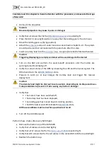
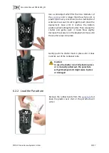
Page 19: ...e holding the shutter Then release the shutter and gently push it inside Now slightly decrease the pressure on the deployment base until the shutter snaps into place Gently push the shutter back in place until it does not stick out of the container tube Caution In case the shutter is not fully back in place or is manually pulled out the parachute will get deployed and might cause injuries or damag...

Page 20: ... the plastic cover Pay special attention to the bottom side Caution Protruding parachute fabric at any side might impede a proper parachute deployment Clip on the container lid to protect the parachute from sunlight and other environmental influences The cord of the parachute should lead out underneath the container lid at its designated position pointing to the center of the UAV when mounted ...

Page 21: ... closed padlock symbol Pull the hook protection sleeve over the hook of the parachute Fit the two hooks into each other I e link the parachute to the UAV Afterwards slide the hook protection sleeve over both hooks Caution The protection sleeve prevents an unintentional detachment of the hooks thus always has to be in place Takeoff Observe the LED and the buzzer during takeoff and thus verify that ...

Page 22: ...does not detect the takeoff you must land the UAV because the automatic deployment function is inactive Switch the power off wait 10 seconds and repeat the start procedure If the failure persists inform Drone Rescue Systems GmbH or it s reseller and provide the logfile for failure analysis After flight After each flight it is recommended to do a short visual overall inspection to see if any part o...

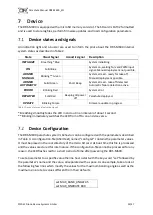
Page 23: ...inking Purple Firmware update in progress Table 2 Device states and indication signals Breathing smoothly fades the LED in and out in an interval of about 1 second Blinking immediately switches the LED from off to on and vice versa Device Configuration The DRS M600 parachute system s behavior can be configured with the parameters described in Table 3 A configuration file ASCII text named config tx...

Page 24: ...bled AUTOMATIC_DISABLE 0 0 1 0 Deploy when enabled parameters exceed their set value 1 System will NOT deploy when enabled parameters exceed set value Only manual deploy works LOGGING_FROM_POWER_ON 1 0 1 0 Logging from takeoff until power off 1 Logging from power on until power off MOTOR_OFF_DELAY 0 0 10000 ms Delay parachute deployment for configured time This refers to manual and automatic deplo...

Page 25: ...y The file will then be renamed to set_time_ok txt on success or set_time_fail txt if the entry cannot be parsed This way the user does not need to manually remove the file after setting the time Firmware Update Store a file bin extension provided by Drone Rescue Systems GmbH in the root directory of the micro SD card to perform a firmware update When the DRS powers up the file will be found and t...

Page 26: ...ph Temperature range 10 C to 40 C Overall weight 450 g 0 99 lbs Maximum number of deployments 10 Minimum deployable altitude 58 90m not including manual deployment within chapter 5 6 Assembly test Results tested at 11 50 kg take off weight Average descent rate 3 92 𝑚 𝑠 14 1 𝑘𝑚 ℎ 8 70 mph Average impact energy 88 3 J 65 0 ft lb Results tested at 15 50 kg take off weight Average descent rate 4 58 𝑚 ...

Page 27: ...y release the tension from the deployment mechanism Always store the container in a dry environment to prevent moisture accumulating inside of the parachute canopy because it will increase the inflation time in case of a deployment 10 Maintenance The parachute rescue system needs to be maintained once a year The maintenance includes the following steps Repacking the parachute Replacement of the pa...

Reviews: