9
ULTRA-SORB MP INSTALLATION, OPERATION, AND MAINTENANCE MANUAL
INSTALLATION
Airflow
Filter
Heating coil
Cooling coil
Duct
high limit
humidity
control
Airflow
proving
switch
Fan
DC-1081_2020
Air handling unit:
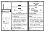
FIGURE 9-1: PLACING A DISPERSION ASSEMBLY IN AN AIR HANDLING UNIT
A
B
AIRFLOW PROVING SWITCH
Ensure placement is representative of air to dispersion device. Sail switch
recommended for variable air volume applications. Pressure switch
recommended for constant volume applications.
DUCT HIGH LIMIT
Place high limit as far downstream as possible but before a duct transition to
prevent wetting again duct walls or other components within the airstream.
General recommendation is 8'-12' (2.4 to 3.7 m) downstream.
PLACEMENT IN AN AIR HANDLING UNIT
• Location A is the best choice. Installing downstream from heating and
cooling coils provides laminar flow through the dispersion unit; plus, the
heated air provides an environment for best absorption.
• Location B is the second-best choice. However, conditions when both
cooling and humidification is needed, the cooling coil will eliminate some
moisture for humidification.
• Calculated absorption distances assume even airflow across entire
dispersion device.
Placement in an air handling unit


