


SECTION 4
OPERATING
Page 38
OM515C520C99/1E
DRESSTA
LOADER OPERATIONS
4.17.4. AUTOMATIC BUCKET LEVELER
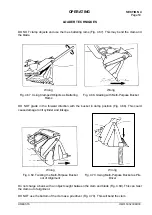
Fig. 4.32. Automatic Bucket Leveler
1. Trip Bar
2. Proximity Switch with Adjustment Nut
C. Bar-To-Switch Clearance
The automatic bucket leveler is located on the underside of the bucket cylinder and is preset to stop
the bucket in the horizontal or digging position. Trip bar (1) is attached to the cylinder rod. The trip
bar moves with the cylinder rod. Proximity switch (2) creates a magnetic field circuit which is
completed by the proximity of trip bar (1) within the magnetic field. Once the bucket is dumped,
move the bucket control lever to its detented "ROLL BACK" position. When the bucket reaches its
preset position, trip bar (1) has moved out of the magnetic field circuit created by the proximity
switch; it will automatically stop and the bucket control lever will return to the "HOLD" position. Bar-
to-switch clearance "C" necessary for the proper operation of the proximity switch is 7 [mm] to 8
[mm]. It is adjusted with the proximity switch nuts.
ADJUSTMENT OF AUTOMATIC BOOM KICK-OUT
Place the bucket flat on the ground. Place the key in the starting switch in the "RUN" position. If the
electromagnetic field of proximity switch (2) is making contact with trip bar (1) mounted under the
cylinder rod, the bucket control lever will stay in the "HOLD" position. Slide the proximity switch
mounting "U" bolt back toward the base end of cylinder until contact of the electro-magnetic field is
broken. This will be the kick-out position for a level bucket.
4.17.5. MULTI-PURPOSE BUCKET CONTROL LEVER POSITIONS (IF
EQUIPPED)
The multi-purpose bucket control lever controls the opening and closing of the clam on the bucket.
Before changing the bucket position raise the bucket 1 [m] above the ground. In standard version it
is located next to the bucket control lever closest to the operator’s seat 28, Fig. 4.4). In upgraded
version it is located on the right of the bucket and boom control lever (28, Fig. 4.5).
OPEN
Push the control lever forward to open the bucket clam. When released, the lever will automatically
return to the "HOLD" position.
HOLD
The control lever will return automatically to the "HOLD" position from either the "OPEN" or
"CLOSE" position when released. The bucket clam will remain in the same position it was in when
the control lever was released.
Summary of Contents for 515C
Page 3: ...OM515C520C99 1E DRESSTA ...
Page 5: ......
Page 7: ......
Page 10: ...SECTION 1 INTRODUCTION ...
Page 12: ......
Page 17: ...SECTION 2 SAFETY PRECAUTIONS ...
Page 19: ......
Page 37: ...SECTION 3 MACHINE TRANSPORT AND STORAGE ...
Page 39: ......
Page 49: ...SECTION 4 OPERATING ...
Page 51: ......
Page 107: ...SECTION 5 MAINTENANCE ...
Page 165: ...SECTION 6 SPECIFICATIONS ...
Page 167: ......
Page 181: ...SECTION 6 SPECIFICATIONS Page 16 OM515C520C99 1E DRESSTA WIRING DIAGRAMS ...
Page 182: ...SPECIFICATIONS SECTION 6 Page 17 DRESSTA OM515C520C99 1E WIRING DIAGRAMS ...
Page 187: ...SECTION 6 SPECIFICATIONS Page 22 OM515C520C99 1E DRESSTA WIRING DIAGRAMS ...