


MAINTENANCE
SECTION 5
Page 49
DRESSTA
OM515C520C99/1E
TRANSMISSION SYSTEM
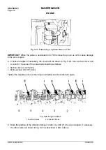
HIGH
LOW
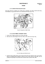
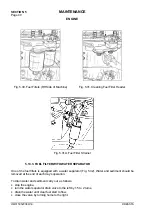
Fig. 5.41. Checking the Transmission Oil Level
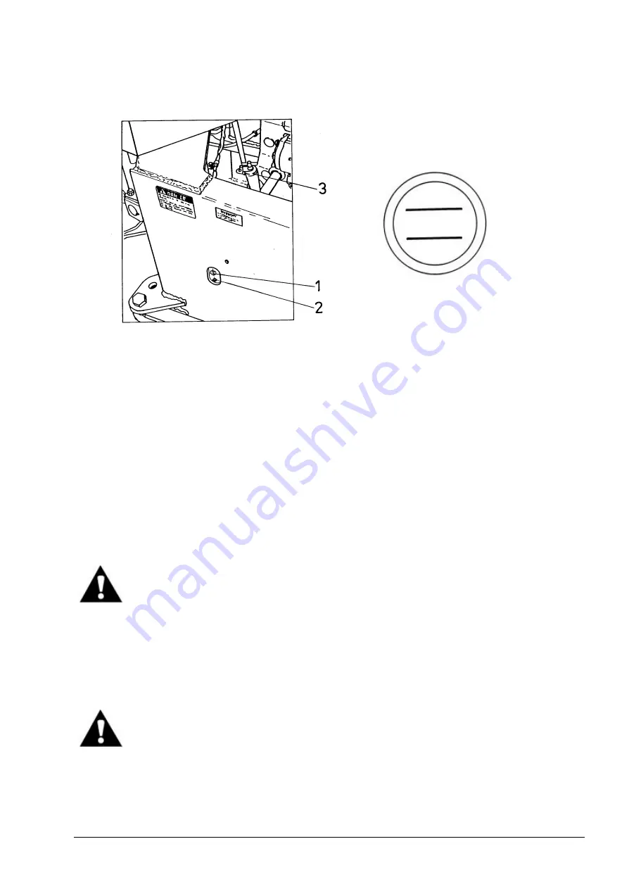
Fig. 5.42. Upper Sight Gauge
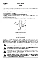
1. Upper Sight Gauge
2. Lower Sight Gauge
3. Filler Plug
4. If the oil level is too low, stop the engine, lock the frame locking bar, remove oil filter cap
(3, Fig. 5.41) and add oil.
5. Start the engine and let it run at low idle.
6. Check the oil level in both sight gauges through the cut-out in the frame (Fig. 5.41). If the oil level
is not between the high and low mark (Fig. 5.42) on the top sight gauge, remove filler cap (3,
Fig. 5.41) and add oil until the level settles in the middle of the upper gauge (maximal level
should not exceed the middle of the upper gauge). Refer to Chart 2 and 3 to choose the proper
oil grade. When refilled reinstall the cap.
IMPORTANT:
If the oil level is above the upper sight gauge, drain the oil until the level is in the
middle of it. Too much oil in the transmission will cause aeration of the oil.
WARNING! Protect your eyes and hands while draining hot oil.
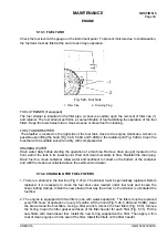
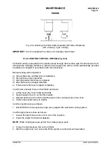
5.18.2. CHANGING THE OIL
1. With the oil at the operating temperature, park the machine on level ground. Lower the bucket to
the ground, apply the parking brake and stop the engine.
2. Install the frame locking bar.
WARNING! Wear hand and eye protection when draining hot fluids.
3. Remove drain plug (1, Fig. 5.43) from the transmission while the oil is still warm.
4. Unscrew transmission oil filler cap (2, Fig. 5.41). This will vent the case and allow the oil to drain
faster.
5. While the oil is draining, service the transmission pressure filter element. Refer to Par. 5.18.3.
6. Service the transmission suction strainer. Refer to Par. 5.18.4.
Summary of Contents for 515C
Page 3: ...OM515C520C99 1E DRESSTA ...
Page 5: ......
Page 7: ......
Page 10: ...SECTION 1 INTRODUCTION ...
Page 12: ......
Page 17: ...SECTION 2 SAFETY PRECAUTIONS ...
Page 19: ......
Page 37: ...SECTION 3 MACHINE TRANSPORT AND STORAGE ...
Page 39: ......
Page 49: ...SECTION 4 OPERATING ...
Page 51: ......
Page 107: ...SECTION 5 MAINTENANCE ...
Page 165: ...SECTION 6 SPECIFICATIONS ...
Page 167: ......
Page 181: ...SECTION 6 SPECIFICATIONS Page 16 OM515C520C99 1E DRESSTA WIRING DIAGRAMS ...
Page 182: ...SPECIFICATIONS SECTION 6 Page 17 DRESSTA OM515C520C99 1E WIRING DIAGRAMS ...
Page 187: ...SECTION 6 SPECIFICATIONS Page 22 OM515C520C99 1E DRESSTA WIRING DIAGRAMS ...