SECTION 4
OPERATING
Page 54
OM515C520C99/1E
DRESSTA
LOADER TECHNIQUES
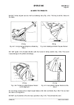
DO NOT try to pick up objects too large to handle (Fig. 4.71). It may damage the bucket and
linkage.
Wrong
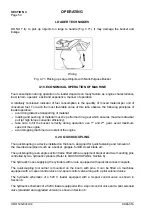
Fig. 4.71. Picking up Large Objects with Multi-Purpose Bucket
4.19. ECONOMICAL OPERATION OF MACHINE
Fuel consumption during operation of a loader depends on many factors as: engine characteristics,
load, terrain, operator’ s skill and experience, manner of operation.
A relatively conclusive indicator of fuel consumption is the quantity of moved material per unit of
consumed fuel. To reach the most favorable value of this ratio observe the following principles of
loader operation:
−
avoid long distance transporting of material,
−
loading and pushing of material must be performed in a gear which ensures maximum drawbar
pull (at high torque converter efficiency),
−
take care to fill the bucket correctly during operation, use 1
st
and 2
nd
gear, avoid maximum
speed of the engine,
−
avoid stopping machine due to stall of the engine.
4.20. QUICKCOUPLING
The quickcoupling is a device installed on the boom, designed for quick fastening and removal of
the mounted equipment such as a bucket, grapple, forklift, dozer blade etc.
The quickcoupling is an angle section frame fitted with an equipment bracket and two mounting pins
controlled by two hydraulic cylinders (Refer to QUICKCOUPLING, Section 6).
The hydraulic hoses supplying the cylinders with oil are equipped with quick disconnect couplers.
The quickcoupling tool carrier is mounted on the boom with pins. It can be fitted on machines
equipped with a 3-spool control valve or 2-spool control valve along with a pilot solenoid valve
The hydraulic schematic of a 520 C loader equipped with a 3-spool control valve is shown in
Section 6.
The hydraulic schematic of a 520C loader equipped with a 2-spool control valve and a pilot solenoid
valve (standard and upgraded version) is shown in Section 6.
Summary of Contents for 515C
Page 3: ...OM515C520C99 1E DRESSTA ...
Page 5: ......
Page 7: ......
Page 10: ...SECTION 1 INTRODUCTION ...
Page 12: ......
Page 17: ...SECTION 2 SAFETY PRECAUTIONS ...
Page 19: ......
Page 37: ...SECTION 3 MACHINE TRANSPORT AND STORAGE ...
Page 39: ......
Page 49: ...SECTION 4 OPERATING ...
Page 51: ......
Page 107: ...SECTION 5 MAINTENANCE ...
Page 165: ...SECTION 6 SPECIFICATIONS ...
Page 167: ......
Page 181: ...SECTION 6 SPECIFICATIONS Page 16 OM515C520C99 1E DRESSTA WIRING DIAGRAMS ...
Page 182: ...SPECIFICATIONS SECTION 6 Page 17 DRESSTA OM515C520C99 1E WIRING DIAGRAMS ...
Page 187: ...SECTION 6 SPECIFICATIONS Page 22 OM515C520C99 1E DRESSTA WIRING DIAGRAMS ...


