800-523-6049
www.rldrake.com
Rev: 0
72820
/ 651239900A
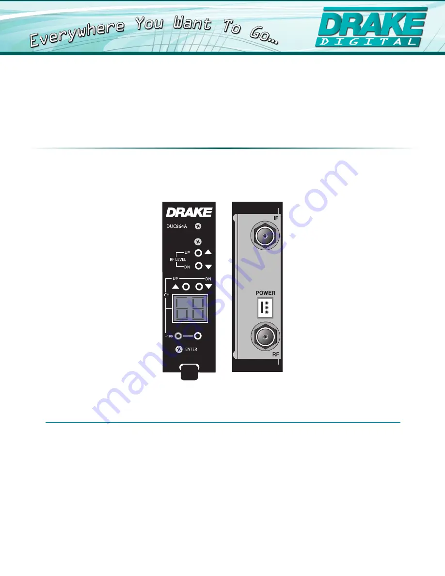
DUC864A
Digital Up-Converter
INSTRUCTION MANUAL
© 2015 R.L. Drake Holdings, LLC.
Model
Item #
Description
1002387A
Page 1: ...800 523 6049 www rldrake com Rev 072820 651239900A DUC864A Digital Up Converter INSTRUCTION MANUAL 2015 R L Drake Holdings LLC Model Item Description DUC864A 1002387A Digital Up Converter ...
Page 2: ...m battery power or other sources refer to the product s operating instructions 12 Grounding or Polarization This product may be equipped with a polarized alternating current line plug a plug having one blade wider than the other This plug will fit into the power outlet only one way This is a safety feature If you are unable to insert the plug fully into the outlet try reversing the plug If the plu...
Page 3: ...et and disconnect the antenna or cable system This will prevent damage to the product due to lightning and power line surges 16 Power Lines An outside antenna system should not be located in the vicinity of overhead power lines other electric light or power circuits where it can fall into such power lines or circuits When installing an outside antenna system extreme care should be taken to keep fr...
Page 4: ...864A IF Input Level 30 dBmV Output Frequency Range Standard CATV IRC HRC Broadcast 54 864 MHz RF Output Level Digital 45 dBmV Display Error 2 dB Output Level Adjustment Range 35 to 45 dBmV Spurious Output 54 864 MHz 60 dBc Phase Noise 10 kHz Offset 95 dBc Hz Broadband Noise Out of Channel 70 dBc 5 5 MHz BW Power Requirement 310 mA 12 VDC 320 mA 5 VDC Average Measurement General Description and Spe...
Page 5: ...ill blink continuously during the channel programming process and will not change the output channel until the ENTER button is depressed b The unit has a special feature that alerts an operator of an inadvertent or desired change to the unit by flashing LED readout The LED will continue to flash for 30 seconds if the ENTER button is not depressed and if no additional entries are made then the read...
Page 6: ...NTER button is not depressed and then will return to the display of the previously programmed channel mode entry setting NOTE The mode presently in memory will be displayed without flashing during the mode selection process A continuously flashing Channel Display indicates an Error Condition detected by the unit microcontroller Sample conditions include Channel Selector Entry does not match the ch...
Page 7: ...333 333 331 75 43 339 339 337 75 44 345 345 343 75 45 351 351 349 75 46 357 357 355 75 47 363 363 361 75 48 369 369 367 75 49 375 375 373 75 50 381 381 379 75 51 387 387 385 75 52 393 393 391 75 53 399 399 397 75 54 405 405 403 75 55 411 411 409 75 56 417 417 415 75 57 423 423 421 75 58 429 429 427 75 59 435 435 433 75 60 441 441 439 75 61 447 447 445 75 62 453 453 451 75 EIA Standard Incremental ...
Page 8: ...e from this product Therefore carefully read the Instruction Manual This warranty does not apply to any defect that R L DRAKE LLC determines is due to 1 Improper maintenance or repair including the installation of parts or accessories that do not conform to the quality and specifications of the original parts 2 Misuse abuse neglect or improper installation 3 Accidental or intentional damage All im...