


Fabius
®
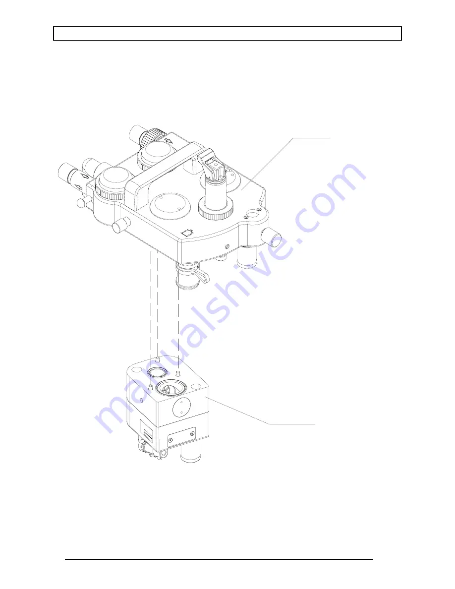
Spare and Replacement Parts
Cop
yr
ight
2000 Dr
aeger
M
edical,
In
c.
sec5_
par
ts
_c.fm
SV00390
COSY ASM (REF.)
SEMI OPEN ADAPTER
Rev. A
5-48
Summary of Contents for Fabius 4116029
Page 2: ...RETURN TO CD ROM TABLE OF CONTENTS RETURN TO THIS MANUAL S TABLE OF CONTENTS ...
Page 6: ...RETURN TO CD ROM TABLE OF CONTENTS RETURN TO THIS MANUAL S TABLE OF CONTENTS ...
Page 8: ...RETURN TO CD ROM TABLE OF CONTENTS RETURN TO THIS MANUAL S TABLE OF CONTENTS ...
Page 68: ...RETURN TO CD ROM TABLE OF CONTENTS RETURN TO THIS MANUAL S TABLE OF CONTENTS ...
Page 234: ...RETURN TO CD ROM TABLE OF CONTENTS RETURN TO THIS MANUAL S TABLE OF CONTENTS ...
Page 318: ...RETURN TO CD ROM TABLE OF CONTENTS RETURN TO THIS MANUAL S TABLE OF CONTENTS ...
Page 324: ...RETURN TO CD ROM TABLE OF CONTENTS RETURN TO THIS MANUAL S TABLE OF CONTENTS ...
Page 326: ...RETURN TO CD ROM TABLE OF CONTENTS RETURN TO THIS MANUAL S TABLE OF CONTENTS ...