


8
5.2.1
Power Connection
The NetGuardian LT G2 is typically powered by a screw terminal barrier plug connector, but other options exist.
Fig. 5.2.2
Screw terminal barrier plug connector
Note
: Always use safe power practices when making power connections. Be sure to remove fuses from the fuse
distribution panel, as well as the back of the NetGuardian LT G2, before making your power connections.
To connect the NetGuardian LT G2 to a power supply:
1. Use the grounding lug to connect the unit to earth ground. The grounding lug is next to the symbol
.
2. Insert the eyelet of the earth ground cable between the two bolts on the grounding lug (Ground cable not
included).
3. Insert a battery ground into the power connector plug's right terminal and tighten the screw.
4. Insert a battery lead to the plug's left terminal and tighten its screw.
5. Insert fuse into the fuse distribution panel.
6. Check the power status LED for polarity.
7. Measure voltage. Connect the black cable onto the ground connector of your DVM.
8. Red cable onto the other connector of your DVM.
9. The voltmeter should read between -36 VDC and -72 VDC.
Note
: If the voltage does not read between -36 VDC and -72 VDC, stop immediately.
10. Insert the local fuse into the power fuse slot. The power plug can be inserted into the power connector only
one way to ensure the correct polarity.
Note
: The negative voltage terminal is on the left and the GND terminal is on the right.
11.Verify that the
LED is lit. To confirm that power is correctly connected, the front panel status LED will
flash RED and GREEN, indicating that the firmware is booting up.
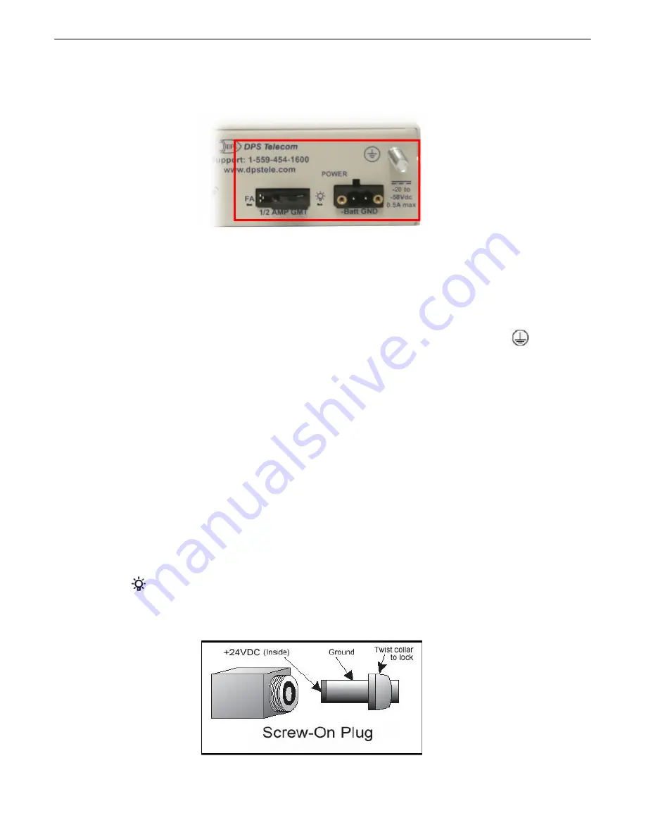
An optional version of the NetGuardian LT G2 is powered by a screw-on plug, as seen in the image below.
Fig. 5.2.3
Close-up view of NetGuardian's screw-on power connector
.
Summary of Contents for D-PK-NGDLT
Page 6: ......
Page 8: ...2 and other summary status...
Page 42: ...36 Fig 11 8 1 View the status of System Alarms from the Monitor System Alarms menu...
Page 83: ...77...
Page 84: ......


