background image

22

Now you're ready

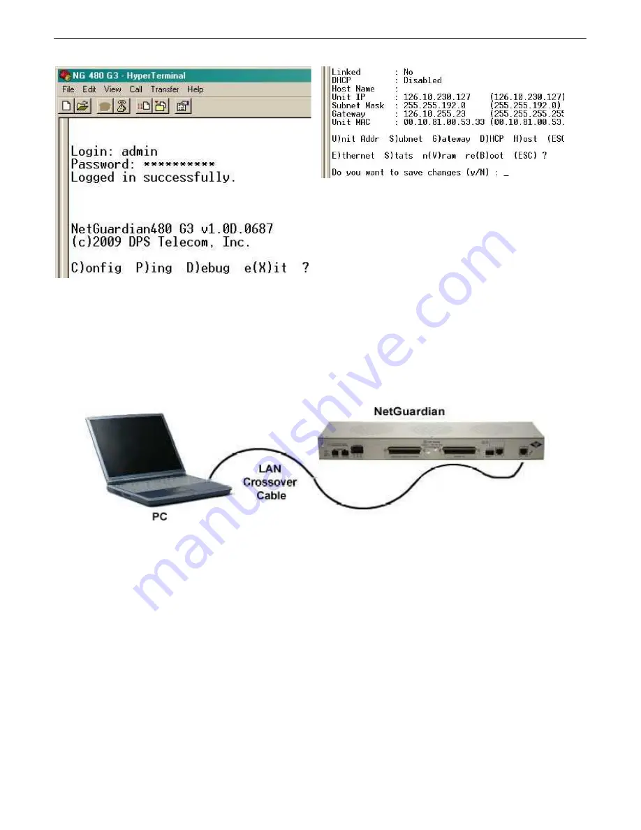
 to do the rest of your configuration via LAN. Plug the NetGuardian into your LAN and

see the "Logging On to the NetGuardian " section to continue databasing using the Web Browser.

NOTE:

 Hold down push button for 20 seconds to bypass TTY login.

...via LAN

7.2

Connection  through  Ethernet port

To connect to the NetGuardian via LAN, all you need is the unit's IP address (Default IP
address is 192.168.1.100).

If you DON'T have LAN, but DO have physical access to the NetGuardian , 

connect using a LAN

crossover  cable. 

NOTE: 

Newer PCs should be able to use a standard straight-through LAN cable and

handle the crossover for you. To do this, you will temporarily change your PC's IP address and subnet
mask to match the NetGuardian's factory default IP settings. Follow these steps:

1.  Get a LAN crossover cable and plug it directly into the NetGuardian 's LAN port. 

2. Look up your PC's current IP address and subnet mask, and write this information down.

3. Reset your PC's IP address to 

192.168.1.200

. Contact your IT department if you are unsure how

to do this.

4. Reset your PC's subnet mask to 

255.255.0.0

. You may have to reboot your PC to apply your

Summary of Contents for D-PK-NG432

Page 1: ...USER MANUAL NetGuardian 480 432 G3 G4 April 22 2019 Visit our website at www dpstelecom com for the latest PDFmanual and FAQs Firmware Version 2 0N D PK NG480 D PK NG432 D UM NG480 NG432 ...

Page 2: ... part without prior written consent fromDPS Telecom except as required by United States copyright laws The material in this manual is for information purposes and is subject to change without notice DPS Telecomshall not be liable for errors contained herein or consequential damages in connection with the furnishing performance or use of this manual Notice Revision History April 22 2019 July 18 201...

Page 3: ...Pinouts 6 4 1 10 NetGuardian 432 G4 Pinouts 6 4 2 11 NetGuardian 480 G3 Pinouts 6 4 3 12 NetGuardian 480 G4 Pinouts 6 4 4 13 Discrete Alarms 6 5 13 Optional 66 Block Connector 6 6 14 D Wire Sensor Input analogs 6 7 15 Analog Step Sizes 6 7 1 15 Quick Start How to Connect to the NetGuardian 7 16 via Craft Port using TTY Interface 7 1 16 via LAN 7 2 22 TTY Interface 8 23 Configure Serial Port via TT...

Page 4: ...ate and Time 10 16 51 Monitoring via the Web Browser 11 52 Alarms 11 1 52 Controls 11 2 53 Sensors 11 3 54 Ping Targets 11 4 55 System Alarms 11 5 56 Graph 11 6 57 Device Access Descriptions 12 59 Firmware Upgrade 13 60 Reference Section 14 61 Front and Back Panel LEDs 14 1 61 Display Mapping 14 2 62 System Alarms 14 3 64 SNMP Manager Functions 14 4 66 SNMP Granular Trap Packets 14 5 68 Frequently...

Page 5: ...cess to on site equipment The NetGuardian also features a reach through serial port This port provides remote users with LAN based Telnet access to a variety of on site telecom equipment including switches radios PBXs and many other devices SNMP or T Mon The NetGuardian can report alarms to any SNMP manager or to the DPS Telecom T Mon Remote Alarm Monitoring System The NetGuardian can also report ...

Page 6: ...16 and 8 lbs Power Input 48VDC 36 to 72 VDC Optional 24 VDC via 110VAC wall transformer 12 to 30 VDC Optional 24VDC 18 to 36 VDC Current Draw 250 mA 24VDC 125 mA 48VDC Fuse Resettable Fuse Internal if 24V Power Input 3 4 Amp GMT Fuse if 48V or 24V Power Input Interfaces 1 RJ45 10 100BaseT full duplex Ethernet port 1 Push button switch Serial port options RS232 RS485 202 33 6 K internal dialup mode...

Page 7: ...r to the part numbers listed and call DPS Telecom at 1 800 622 3314 NetGuardian D PK NG480 or D PK NG432 NetGuardian User Manual NetGuardian Resource CD D UM NG480 NG432 USB Cable 14 ft Ethernet Cable D PR 046 10A 06 D PR 923 10B 14 23 Rack Ears 19 Rack Ears D CS 325 10A 01 D CS 325 10A 00 x8 x4 3 8 Ear Screws Rack Screws and Lock Washers 1 000 12500 06 2 000 60375 05 ...

Page 8: ... 4 Pin Serial Connector 202 Option Only Included on WAGO Builds 2 820 00814 02 2 802 04037 00 x 2 Hex Nut Ships mounted on grounding lug 2 002 01024 00 Optional Shipping Items Available by Request 3 1 24V Wall Transformer Telephone Cable 6ft D PR 105 10A 02 D PR 045 10A 01 110VAC to 24VDC converter For Optional Modem Build Only DPS D Wire Sensors D PK DSNSR 12XXX Multiple sensor options available ...

Page 9: ...Terminal Mounting 4 2 The NetGuardian 480 can be flush or rear mounted The NetGuardian 480 mounts in a 19 rack or a 23 rack using the provided rack ears for each size Two rack ear locations are provided Attach the appropriate rack ears in the flush mount or rear mount locations shown in Figure 6 2 1 Note Rack ears can be rotated 90 for wall mounting or 180º for other mounting options not shown ...

Page 10: ...6 NetGuardian Front Panel 5 NetGuardian 432 G3 NetGuardian 432 G4 NetGuardian 480 G3 NetGuardian 480 G4 ...

Page 11: ...7 NetGuardian Back Panel 6 NetGuardian 432 G3 back panel connections NetGuardian 432 G4 back panel connections NetGuardian 480 G3 back panel connections NetGuardian 480 G4 back panel connections ...

Page 12: ...tery ground into the power connector plug s right terminal and tighten the screw then insert a battery line to the plug s left terminal and tighten its screw 4 Insert a fuse into the fuse distribution panel and measure voltage The voltmeter should read between 40 and 70VDC for 48VDC build option 18 and 36VDC 24VDC build option or 18 and 36VDC 24VDC build option 5 The power plug can be inserted int...

Page 13: ... on the back panel Hot Tip If you are unsure of the serial port type on your NetGuardian login to MyDPS and click on the Product Information Search link Type in the full part number of your unit and click the Submit button to access the specifications The serial port can be used for different functions Reach through proxy connection for LAN based Telnet access to switches radios PBXs and other equ...

Page 14: ...ctors 6 4 6 4 1 NetGuardian 432 G3 Pinouts NetGuardian 432 G3 Alarm and Relay Connectors The connectors for discrete alarms and control relays is the 50 pin connector on the NetGuardian s back panel NetGuardian 432 G3 Amphenol pinout ...

Page 15: ...11 6 4 2 NetGuardian 432 G4 Pinouts NetGuardian 432 G4 Alarm and Relay Connectors NetGuardian 432 G4 Amphenol pinouts ...

Page 16: ...rdian 480 G3 Pinouts NetGuardian 480 G3 Alarm and Relay Connectors The connectors for discrete alarms and control relays are the two 50 pin connectors on the NetGuardian s back panel NetGuardian 480 G3 Amphenol pinout ...

Page 17: ...13 6 4 4 NetGuardian 480 G4 Pinouts NetGuardian 480 G4 Alarm and Relay Connectors NetGuardian 480 G4 Amphenol pinouts Discrete Alarms 6 5 To generate an alarm tie the ALM pin to the RTN pin ...

Page 18: ...t and color code information see the diagrams below Note The 66 Block supports termination of 22 26 AWG 0 81 0 41mm solid insulated cable or 18 19 AWG 1 02 0 91mm solid stripped cable DPS recommends using 24 AWG wire solid NetGuardian 480 G3 66 block connections for discretes 49 80 and control relays 1 4 left amphenol 66 block connections for discretes 1 48 right amphenol ...

Page 19: ... 2 of your NetGuardian s 16 analog channels the combined temp humidity sensor D PK DSNSR 12002 for example Your NetGuardian can provide power to a sensor chain up to 800 feet long The Integrated temperature build option uses one of the maximum 16 sensors that are supported The D Wire line of sensors includes temp humidity additional analogs discretes and more Contact DPS at 1 800 693 0351 for info...

Page 20: ...y from your PC to the NetGuardian and access its Web Browser See the via LAN section of this chapter via Craft Port using TTY Interface 7 1 1 The simplest way to connect to the NetGuardian is over a physical cable connection between your PC s USB port and the unit s USB craft port Note You must be connected via craft port or Telnet to use the TTY interface Make sure you are using a standard A B US...

Page 21: ... message will appear 1 Click the Found New Hardware message icon to launch the Found New Hardware Wizard 2 Select Install from a list or specific location Advanced 3 Click Next 4 Select Search for the best driver in these locations 5 Insert NetGuardian Resource Disc CD into your PC ...

Page 22: ...g message will confirm installation of a new USB Communications Port 8 Click Finish to close the Wizard Now that the driver has been installed a new COM port is being emulated on your PC Before using hyperterminal you must confirm the identity of that new COM port COM1 COM2 COM3 in the Windows Device Manager ...

Page 23: ...19 9 Right click the My Computer icon on your desktop then click Manage 10 Click Device Manager in the left pane ...

Page 24: ...nch HyperTerminal or other terminal software 12 Click on the Start menu select Programs Accessories Communications HyperTerminal 13 At the Connection Description screen enter a name for this connection You may also select an icon The name and icon do not affect your ability to connect to the unit 14 At the Connect To screen use the drop down menu to select the COM port you found earlier in the Dev...

Page 25: ...lecom NOTE If you don t receive a prompt for your user name and password check the Com port you are using on your PC and make sure you are using the cable provided Additional cables can be ordered from DPS Telecom 17 The NetGuardian s main menu will appear Type C for C onfig then E for E thernet Configure the unit s IP address subnet mask and default gateway 18 ESC to the main menu When asked if y...

Page 26: ...e NetGuardian connect using a LAN crossover cable NOTE Newer PCs should be able to use a standard straight through LAN cable and handle the crossover for you To do this you will temporarily change your PC s IP address and subnet mask to match the NetGuardian s factory default IP settings Follow these steps 1 Get a LAN crossover cable and plug it directly into the NetGuardian s LAN port 2 Look up y...

Page 27: ...g other devices on the network Set unit back to factory defaults Debug and troubleshoot For more advanced configuration tools please use the Web Browser Interface For Telnet connect to the IP address at port 2002 to access the configuration menus after initial LAN WAN setup Telnet sessions are established at port 2002 not the standard Telnet port as an added security measure If you re using Window...

Page 28: ...2 Press the hot keys to toggle through the following options Indicates default settings NOTE Default settings may not reflect the primary interface that shipped in the unit Port Type 232 485 Baud 9600 57600 19200 9600 4800 2400 1200 Parity None even odd Stop bits 1 2 3 Set the RTS head tail Carrier time Suggested settings are 0 0 if using RS232 ...

Page 29: ... use for this notification Now select the Send Email button and click Save and Next 3 At the Email Notification screen you ll enter your email server settings Enter the IP address or Host Name of your email server Note if using Host Name make sure that DNS Servers settings are configured Enter the Port Number usually 25 and the To Email Address of the technician that will receive these emails If a...

Page 30: ...otification to an alarm point See the next step 6 Now you will associate this notification to an alarm system base analog etc You have 8 notification devices available to use In the image below you might assign Notification Device 1 to Alarm 1 This means that you would receive an email notification when Temperature Threshold 1 Alarm Point 1 occurs Remember that Notification 1 in the Notifications ...

Page 31: ...fault dps_public 2 Click on the Notifications button in the Provisioning menu You can setup as many as 8 different notifications Begin the setup wizard by clicking Edit for a notification number In this example we ll setup Notification 1 to send SNMP traps to your alarm master 3 At the SNMP Notification screen you ll enter your network s SNMP settings Enter the IP address of your SNMP Trap Server ...

Page 32: ...m the drop down menus Click Save and Finish To try a test notification click the Test button See next step 5 If you chose to test the email notification you ve just setup you will prompted with a pop up Click OK to send a test SNMP alarm notification Confirm all your settings by checking your alarm master to see if the SNMP trap was received NOTE This test only means that your notification setting...

Page 33: ...cally The web interface will then prompt you to either Write your changes to the unit or Reboot the unit for changes to take effect in the top left corner of your browser The relevant options will be highlighted in the Device Access options Note If the unit prompts you to both Write changes to the unit and Reboot you will Write your changes first Rebooting without writing to the unit if a Write is...

Page 34: ...u DCP Responder Settings For use with T Mon Disable DCP DCP over LAN Serial Select one of these 3 options to send DCP protocol over LAN serial or disable DCP completely DCP Unit ID User definable ID number for the target unit DCP Address DCP Unit Protocol Drop down menu of available protocols for use with DCP Address DCP over LAN port Enter the DCP port for the target unit UDP TCP port LAN Protoco...

Page 35: ... profiles and password information Write Config change unit configuration Enables the user to change the unit config by accessing the Write feature in the control menu View monitor pages Allows the user to access Monitor menu options Send relay commands Allows the user to send commands to operate the device s control relays TTY access access via Craft port or via Telnet Grants the user access to t...

Page 36: ...means the unit will NOT operate in a T Mon environment Unit IP IP address of the NetGuardian Subnet Mask A road sign to the NetGuardian telling it whether your packets should stay on your local network or be forwarded somewhere else on a wide area network Gateway An important parameter if you are connected to a wide area network It tells the NetGuardian which machine is the gateway out of your loc...

Page 37: ...S server should retry a logon attempt Time out Enter in the number of seconds before a logon request is timed out Servers 1 2 IPA Enter the IP address of the RADIUS server Port Port 1812 is an industry standard port for using RADIUS Secret Enter the RADIUS secret in this field After successfully entering the settings for the RADIUS server the NetGuardian Web Browser will prompt users for both a Us...

Page 38: ...ect the appropriate settings from the drop down menu RTS Head Only used if your NetGuardian was built with a 202 modem The most commonly used value is 30 RTS Tail Only used if your NetGuardian was built with a 202 modem The most commonly used value is 10 Reach Through Enable Reach through Checking this box enables the port to be used as a terminal server Most commonly used to Telnet through the po...

Page 39: ...or SNMP SET requests Read and Write Access This field defines how the NetGuardian may be accessed via SNMP This can be set to the following Access Disabled Restricts all access to unit via SNMP SNMPv2c only Allows SNMPv2c access only SNMPv2c and SNMPv1 Only Allows SNMPv1 and SNMPv2c access SNMPv3 SNMPv2c and SNMPv1 Allows SNMPv3 SNMPv2c and SNMPv1 access Fields in the Provisioning SNMP settings ...

Page 40: ...server to receive emails usually set to 25 Use SSL Check this box to use SSL encryption Currently this feature has been tested with Gmail To send with Gmail SMTP server do the following SMTP Server IP or Host Name should be set to smtp gmail com Port number must be set to 465 SMTP authentication radio button must be selected User name and password below under How to Authenticate are the user name ...

Page 41: ...traps 10 7 2 Schedule The notifications scheduling menu is where you will tell the NetGuardian exactly which days and times you want to receive alarm notifications You set 2 different schedules for each The Schedule creation screen Notification Scheduling Days of the week From either Schedule 1 or 2 check which days you want to receive notifications Any Time Select this is if you want to receive a...

Page 42: ...n un checked means a normally open contact closure is an alarm When polarity is reversed a normally closed alarm point is clear when closed Notification Devices Check which notification device s 1 through 8 you want to send alarm notifications for that alarm point Advanced Alarm Configuration Advanced On Set User definable description condition that will appear for the discrete alarm input on Set ...

Page 43: ...on device s The Provisioning Exp Controls screen Basic Controls Configuration ID ID number for the control relay Description User definable description for the NetGuardian s control relay Momentary Time Control on time in milliseconds when you execute the MOM command Max limit of 600 seconds Notification Devices Check which notification device s 1 through 8 you want to send alarm notifications for...

Page 44: ...syntax of the equation Configure derive Controls in the Edit menu Controls screen Details Derived Description _OR Set the current operation to OR _AN Set the current operation to AND _XR Set the current operation to XOR D Tag to change the active display number Used like a comma to delimit numbers Used to specify a range of points Spaces included here are for readability purposes only Hot Tip Prec...

Page 45: ... 4 1 5 2 6 2 7 3 10 3 12 10 9 2 Derived Expansion Controls Derived expansion controls have the same functionality as derived controls They are used for the expansion unit such as the NetGuardian E16 DX G2 Configure derive Controls in Provisioning Expansion Controls ...

Page 46: ...umber found on the sticker of the temperature sensor node Your NetGuardian will automatically detect the sensor ID when you plug a sensor into the unit The color of the sensor ID field will tell you the status of the connected sensor Green The sensor is connected and properly configured Yellow The sensor is connected but has not yet been configured fill in your configuration fields and click Save ...

Page 47: ...nuously If the evaluation changes at any point the sensor s value increases by an increment of 1 This mode can be useful for counting the number of times a discrete input toggles Evaluation Sensor every tenth of a minute 6 seconds evalMt The equation is evaluated every 6 seconds and its result becomes the sensor s value Evaluation Sensor every minute evalMn The equation is evaluated every 60 secon...

Page 48: ...ack and are used to perform the operation the first item popped is the SECOND operand The result of the operation is then pushed onto the stack This repeats until the end of the equation is reached An equation is valid only if there is exactly ONE item left in the stack when the end of the equation is reached Example of how an equation is evaluated Equation a8 a5 a6 a4 Input Operation Stack Commen...

Page 49: ...ing Targets menu Provisioning Ping Targets ID ID number for the ping target Enab Check this box to enable the ping target Description User definable description for the ping target Server IP or Hostname IP address or hostname of the device you would like to ping Notification Devices Check which notification device s 1 through 8 you want to send alarm notifications for ping target ...

Page 50: ...46 Modbus Devices 10 12 The Provisioning Modbus Devices ...

Page 51: ...for polling when using TCP Modbus Unused otherwise TCP Port or Serial Port TCP or physical serial port used when performing Modbus polling Modbus Address Address of Modbus device Device Register Offset Amount to offset Modbus Address by Threshold Mode This will configure different threshold values based on Modbus register values Threshold mode options 1 standard thresholds default threshold settin...

Page 52: ...48 Modbus Registers 10 13 The Provisioning Modbus Registers ...

Page 53: ... bits used to mask the response value Integer Float Interpret response value as an integer for a float Unsigned Signed Interpret the response value as signed or unsigned Byte Order Byte ordering of response from Modbus device Scaling Scaling factor that the response value is multiplied by Units Units displayed with the response value Thresholds MjU Major Under MnU Minor Under MnO Minor Over MjO Ma...

Page 54: ...m point number Description Non editable description for this System housekeeping Alarm Silence Check this box to choose to silence this alarm Notification Devices Check which notification device s 1 through 8 you want to send alarm notifications for that alarm point Timers 10 15 Enter the amount of time in seconds sec or minutes m in each value field and click Save The Provisioning Timers menu ...

Page 55: ...address or host name then click Sync Example us pool ntp org Note Make sure to configure DNS before using host name instead of IP address Time Zone Select your time zone from the drop down menu Adjust Clock for Daylight Savings Time DST Enable DST Check this box to have the NetGuardian 480 observe Daylight Savings Start Day Select the month weekday and time when Daylight Savings will begin End Day...

Page 56: ...s will appear in red if an alarm has been activated The status will be displayed in green when the alarm condition is not present Click on Alarms or Exp Alarms in the Monitor menu to see if any discrete alarms have been triggered Expansion Alarm Monitoring ID Alarm ID number Description User definable description for the discrete alarm point State The current state of the alarm Clear or Alarm ...

Page 57: ...ew and operate control relays from the Monitor Exp Controls menu Expansion Control Relay Operation ID ID number for the control relay Description Description for the NetGuardian s control relay defined in the Provisioning Controls menu State Status of the control relay Can either be Released or Latched Command OPR Latch the relay RLS Release the relay MOM Momentarily latch the relay then automatic...

Page 58: ...ption of each analog channel the current reading the units being read and alarm conditions major under minor under major over minor over according to your temperature settings If configured under Provisioning Sensors your analog values will be displayed as a graphical gauge Selecting Table View will display a non graphical interface of your values The Monitor Sensors menu ...

Page 59: ... 4 Ping Targets can be viewed by going to Monitor Ping Targets Here you can view the state either Clear or Alarm for each of your configured Ping Targets View the status of Ping Targets from the Monitor Ping Targets menu ...

Page 60: ...indicating if an alarm has been triggered Under the State column the status will appear in red if an alarm has been activated The status will be displayed in green when the alarm condition is not present See Display Mapping in the Reference Section for a complete description of system alarms View the status of System Alarms from the Monitor System Alarms menu Monitor Alarm History menu ...

Page 61: ...ut trending values To create your Graph specify the Channel Sensors 1 32 Group Interval 1 120 minutes hours days or weeks the Group Function Average Min Max and Start End Times Once you have entered all of the desired values click Build Graph Provision the Channels Group Interval Group Function and more all from the Graph Parameters section of the web browser interface ...

Page 62: ...se over the lines to quickly view measurements date time and value within their context of the overall graphing trend Below the graph is a full textual list of all indexed points with their dates and values Specify your parameter values and build an interactive graph based on the alarm point history ...

Page 63: ...ocated in the bottom left of the web interface Device Access Option Description Backup Config Backs up the units configuration settings Read Reads a configuration file from the unit Write Commits all changes made in the web interface to the NetGuardian s non volatile memory Initialize Sets the unit s configuration to factory default values Get Log Opens the NetGuardian s event log in Notepad or an...

Page 64: ... the Firmware Load screen click on the Upload link in the top right corner At the Firmware Load screen simply browse for the firmware update you ve downloaded from www dpstele com and click Load Browse for downloaded firmware upgrade ...

Page 65: ...lashing Red New alarm Solid Red Standing alarm acknowledged Relay Solid Green 1 or more control relays latched Tune 202 Solid Green NG is in 202 modem Tuning Mode Front Panel LED Descriptions Back panel LEDs LED Status Description A Solid Green Power supply A OK Off No voltage or 24V and GND leads reversed on Power supply A B Solid Green Power supply B OK Off No voltage or 24V and GND leads revers...

Page 66: ...y 6 Digital Temp Sensor 3 Minor Under 99 1 1 Digital Temp Sensor 3 Minor Over 99 1 2 Digital Temp Sensor 3 Major Under 99 1 3 Digital Temp Sensor 3 Major Over 99 1 4 Digital Temp Sensor 3 Sensor not detected 99 1 5 Control 99 1 9 16 Value 99 1 17 32 Display 7 Digital Temp Sensor 4 Minor Under 99 1 1 Digital Temp Sensor 4 Minor Over 99 1 2 Digital Temp Sensor 4 Major Under 99 1 3 Digital Temp Senso...

Page 67: ... 9 16 Value 99 1 17 32 Display 13 Digital Temp Sensor 10 Minor Under 99 1 1 Digital Temp Sensor 10 Minor Over 99 1 2 Digital Temp Sensor 10 Major Under 99 1 3 Digital Temp Sensor 10 Major Over 99 1 4 Digital Temp Sensor 10 Sensor not detected 99 1 5 Control 99 1 9 16 Value 99 1 17 32 Display 14 Digital Temp Sensor 11 Minor Under 99 1 1 Digital Temp Sensor 11 Minor Over 99 1 2 Digital Temp Sensor 1...

Page 68: ...gital Temp Sensor 16 Major Over 99 1 4 Digital Temp Sensor 16 Sensor not detected 99 1 5 Control 99 1 9 16 Value 99 1 17 32 Display 20 Expansion 1 Alarms 1 64 99 1 1 64 Display 21 Expansion 1 Controls 1 16 99 1 1 16 Undefined 99 1 17 64 Note Digital Temp Sensor Value must be multiplied by the appropriate VBIT from table 14 2 in order to create a displayable Value Display Mapping System Alarms 14 3...

Page 69: ... unsuccessful Use RPT filter debug to help diagnose notification problems 51 Expansion 1 Failed Expansion shelf 1 communication link failure Verify the number of configured NGDdx units Use EXP filter debug and port LEDs to help diagnose the problem Verify the addressing on the NGDdx unit 57 Default Configuration The internal NVRAM may be damaged The unit is using default configuration settings Log...

Page 70: ... has several levels above it The full English name is as follows root iso org dod internet private enterprises dps Inc dpsAlarmControl dpsRTU Therefore dpsRTU s full object identifier is 1 3 6 1 4 1 2682 1 2 Each level beyond dpsRTU adds another object identifying number For example the object identifier of the Display portion of the Control Grid is 1 3 6 1 4 1 2682 1 2 3 3 because the object iden...

Page 71: ...equest which will resend TRAPs for any standing alarm Tbl B3 2 DisplayGrid points DisplayEntry 1 3 6 1 4 1 2682 1 2 2 1 Port 1 Address 2 Display 3 DispDesc 4 PntMap 5 Tbl B3 3 ControlGrid points ControlGrid 1 3 6 1 4 1 2682 1 2 3 Port 1 Address 2 Display 3 Point 4 Action 5 Tbl B6 6 Analog Channels Channel Entry 1 3 6 1 4 1 2682 1 4 6 1 Channel Number 1 Enabled 2 Description 3 Value 4 Thresholds 5 ...

Page 72: ...ption 0 Version Public Request Trap Request 1 3 6 1 4 1 2682 1 4 Enterprise 126 10 230 181 Agent address Enterprise Specific Generic Trap 8001 Specific Trap 617077 Time stamp 1 3 7 1 2 1 1 1 0 Object NetGuardian 480 v1 0K Value 1 3 6 1 2 1 1 6 0 Object 1 800 622 3314 Value 1 3 6 1 4 1 2682 1 4 4 1 0 Object 01 02 1995 05 08 27 760 Value 1 3 6 1 4 1 2682 1 4 5 1 1 99 1 1 1 Object 99 Value 1 3 6 1 4 ...

Page 73: ... the default gateway A sample configuration could look like this Unit Address 192 168 1 100 subnet mask 255 255 255 0 Default Gateway 192 168 1 1 Save your changes by writing to NVRAM and reboot Any change to the unit s IP configuration requires a reboot Q When I connect to the NetGuardian through the craft port on the front panel it either doesn t work right or it doesn t work at all What s going...

Page 74: ...ormation when you call our Technical Support representatives can assist you in gathering it Please write the information down for easy access Please have your user manual and hardware serial number ready 3 Have access to troubled equipment Please be at or near your equipment when you call DPS Telecom Technical Support This will help us solve your problem more efficiently 4 Call during Customer Sup...

Page 75: ...71 ...

Page 76: ...hold it harmless for and against any and all claims damages losses costs expenses obligations liabilities fees and costs and all amounts paid in settlement of any claim action or suit which may be asserted against DPS Telecom which arise out of or are related to the non fulfillment of any covenant or obligation of End User in connection with this Agreement This Agreement shall be construed and enf...

Page 77: ...73 ...

Page 78: ......

Page 79: ... lightning unless and to the extent that the product specification provides for resistance to a defined disaster e damage caused by unauthorized attachments or modifications f damage during shipment fromthe purchaser to DPS or g any abuse or misuse by the purchaser THE FOREGOINGWARRANTIES ARE IN LIEU OF ALL OTHER WARRANTIES EXPRESS OR IMPLIED INCLUDINGBUT NOT LIMITED TO THE IMPLIED WARRANTIES OF M...

Page 80: ...uct manuals Product datasheets Exclusive user forms Expert tips on using your alarm monitoring equipment advanced techniques that will save you hours of work Educational White Papers deliver fast informal tutorials on SNMP ASCII processing TL1 and other alarm monitoring technologies New product and upgrade announcements keep you up to date with the latest technology Exclusive access to special off...

Reviews: