22 / 96
– Bluetooth LE interface for app connection DP Control App
– LEDs for signalling the operating status
– 2 volt-free contacts on terminals are provided for reporting warnings and alerts.
– Manual-0-automatic selector switch per pump (optional)
4.6 Configuration and function
1
2
3
4
5
6
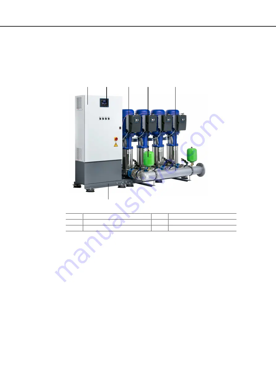
Fig. 5:
Configuration Utility Line VC
1
Control cabinet
4
Membrane-type accumulator
2
Control unit
5
Manifold
3
Pump
6
Baseplate
Design
Fully automatic pressure booster system with two to six vertical high-pressure pumps (3) for
ensuring the required supply pressure.
Function
Utility Line F:
Two to six pumps are controlled and monitored by a microprocessor control unit (DP
Control). The first pump is started up when the pressure falls below the set start-up pressure
(setpoint minus half bandwidth). Additional pumps are sequenced in automatically in line
with actual demand. When demand decreases, the pumps are sequenced out again as the
stop pressure (setpoint plus half bandwidth) is reached. The pump that has been started up
first will be stopped first. The pumps are automatically started up in a different order for each
new cycle. The actual pressure is measured by an analog pressure transmitter. The function
of this pressure transmitter is monitored (broken wire detection).
This ensures equal distribution of pump operating hours.
Utility Line VC, SVP:
Two to six pumps are controlled and monitored by a microprocessor control unit (DP
Control). Each pump is operated on a frequency inverter and controlled by the control unit
so as to ensure a constant discharge pressure of the pressure booster system.
As the demand increases or decreases, peak load pumps are started and stopped
automatically. As soon as the demand increases again after one pump has been stopped,
another pump which has not been in operation before is started up. When the last pump has
been stopped and the demand increases again, the next pump in line is started up on a
frequency inverter. The stand-by pump is also included in the alternating cycle.
Summary of Contents for Hydro-Unit Utility Line F
Page 29: ...29 96 1 2 Fig 12 PE connection 1 Earthing terminal 2 Location of power connection ...
Page 58: ...58 96 ...
Page 92: ...92 96 T Tank 79 Timers 73 W Warnings 9 Warranty claims 7 ...
Page 93: ......
Page 94: ......
Page 95: ......


