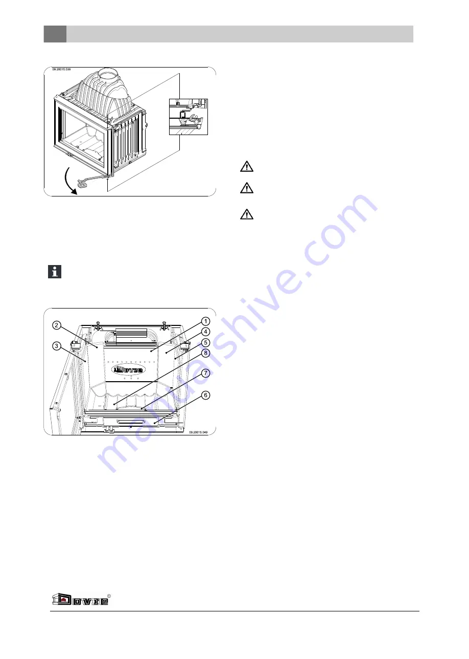
2. First take the inner plates (3) and (5) out of the
appliance.
3. Then take the inner plates (2) and (4) out of the
appliance.
4. Lastly, take the inner plate (1) out of the appliance.
Cast iron inner plates protect the combustion
chamber and dissipate heat to the
environment.
Removable internal sections
1
Inner plate back middle
2
Inner plate back left
3
Left-hand side inner plate
4
Inner plate back right
5
right-hand side inner plate
6
ash pan
7
ash removal port
8
bottom of the fire compartment
Connecting the fan to the mains
The fireplace insert is supplied with a built-in fan and
with a separate revolution control unit. The appliance
is also fitted with a thermoswitch that turns the fan on
and off at a set temperature. These parts must be
connected to the mains as shown in the connection
diagram in Appendix 1.
Have the connection made by a qualified installer.
The stove is provided with a three-core cable.
The fireplace insert must be isolated from the
mains by a 2-pole switch.
Ensure that the stove is properly earthed.
Fitting the outside air intake
duct
If the appliance is installed in a room without sufficient
ventilation, you can install the connecting kit on the
appliance for the supply of outside air.
The air supply tube has a diameter of 100 mm. If
installing a smooth tube, it may be no longer than 12
m. If accessories such as bends are used, the
maximum length (12 m) must be reduced by 1 m for
each accessory used.
Outside air intake duct through the
wall or the floor and the flue collar
1. Make a hole in the wall or the floor (refer to
Appendix 2, "Dimensions" for a suitable position
of the hole).
2. Fit the air intake duct airtight to the wall.
3. Fit the flue collar (A) to the M6 stud (B) using the
nut (D) and the lock washer (C); see next figure.
8
Subject to change because of technical improvements


