WIL-12620-E-07
Where Innovation Flows
EOM
ENGINEERING OPERATION & MAINTENANCE MANUAL
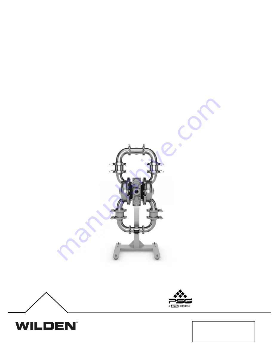
PS8 Saniflo™ Hygienic™ Series Clamped Metal Pump
Page 1: ...WIL 12620 E 07 Where InnovationFlows EOM ENGINEERING OPERATION MAINTENANCE MANUAL PS8 Saniflo Hygienic Series Clamped Metal Pump ...
Page 2: ... PSG California LLC Wil Flex is a trademark of PSG California LLC Saniflex is a trademark of PSG California LLC All trademarks names logos and service marks collectively trademarks in this document are registered and unregistered trademarks of their respective owners Nothing contained in this document should be construed as granting any license or right to use any trademark without the prior writt...
Page 3: ...ke Integral Piston Diaphragm Fitted 10 PS8 Saniflo HS PTFE Integral Piston Diaphragm Fitted 11 Suction Lift Capability 12 SECTION 6 Suggested Installation Operation Maintenance and Troubleshooting 13 SECTION 7 Disassembly Reassembly 16 Pump Disassembly 16 Wil Gard Diaphragm Sensor 19 Swivel Pump Stand Option 20 Air Valve Center Section Disassembly 21 Single Point Exhaust 24 Reassembly Hints and Ti...
Page 4: ...cally with all wetted pump components CAUTION Before attempting any maintenance or repair disconnect the compressed air line to the pump and allow all air pressure to bleed from the pump Disconnect all intake discharge and air lines Drain the pump by turning it upside down and allowing any fluid to flow into a suitable container Be aware of any hazardous effects of contact with your process fluid ...
Page 5: ... Connection 0782 Saniflo HS Wil Gard 110V w Swivel Stand DIN Connection 0783 Saniflo HS Wil Gard 220V w Swivel Stand DIN Connection 0784 Saniflo HS SMS Connection 0785 Saniflo HS w Swivel Stand SMS Connection 0786 Saniflo HS Wil Gard 110V SMS Connection 0787 Saniflo HS Wil Gard 220V SMS Connection 0788 Saniflo HS Wil Gard 110V w Swivel Stand SMS Connection 0789 Saniflo HS Wil Gard 220V w Swivel St...
Page 6: ...f its seat while the opposite discharge valve ball is forced onto its seat forcing fluid to flow through the pump discharge The movement of diaphragm A toward the center of the pump creates a vacuum within liquid chamber A Atmospheric pressure forces fluid into the inlet manifold of the pump The inlet valve ball is forced off its seat allowing the fluid being pumped to fill the liquid chamber FIGU...
Page 7: ...H 386 15 2 J 380 15 0 K 586 23 1 L 580 22 9 M 584 23 0 N 400 15 8 P 349 13 8 R 318 12 5 S 356 14 0 T ø10 ø0 4 LW0247 REV C PS8 SANIFLO HYGIENIC SERIES FIXED STAND FLAP VALVE DIMENSIONS ITEM METRIC mm STANDARD inch A 460 18 1 B 167 6 6 C 595 23 4 D 963 37 9 E 1010 39 8 F 51 2 0 G 57 2 2 H 386 15 2 J 380 15 0 K 586 23 1 L 580 22 9 M 584 23 0 N 400 15 8 P 349 13 8 R 318 12 5 S 356 14 0 T ø10 ø0 4 LW0...
Page 8: ... 20 5 J 514 20 3 K 721 28 4 L 715 28 2 M 611 24 1 N 400 15 8 P 349 13 8 R 394 15 5 S 732 17 0 T ø10 ø0 4 LW0248 REV C PS8 SANIFLO HYGIENIC SERIES SWIVEL STAND FLAP VALVE DIMENSIONS ITEM METRIC mm STANDARD inch A 460 18 1 B 194 7 6 C 623 24 5 D 990 39 0 E 1038 40 9 F 51 2 0 G 57 2 2 H 522 20 5 J 514 20 3 K 721 28 4 L 715 28 2 M 611 24 0 N 400 15 8 P 349 13 8 R 394 15 5 S 432 17 0 T ø10 ø0 4 LW0250 ...
Page 9: ...ers will fall in the center of the pump s performance curve Caution Do not exceed 8 6 bar 125 psig air supply pressure PS8 SANIFLO HYGIENIC SERIES EZ INSTALL TPE FITTED Ship Weight 49 kg 109 lb Air Inlet 19 mm 3 4 Inlet 51 mm 2 Outlet 51 mm 2 Suction Lift 4 0 m Dry 13 1 9 0 m Wet 29 5 Disp Per Stroke1 1 0 L 0 27 gal Max Flow Rate 571 lpm 151 gpm Max Size Solids Mushroom Valve 6 4 mm 1 4 Ball Valve...
Page 10: ...ll in the center of the pump s performance curve Caution Do not exceed 8 6 bar 125 psig air supply pressure PS8 SANIFLO HYGIENIC SERIES FULL STROKE INTEGRAL PISTON DIAPHRAGM FITTED Ship Weight 49 kg 109 lb Air Inlet 19 mm 3 4 Inlet 51 mm 2 Outlet 51 mm 2 Suction Lift 3 2 m Dry 10 6 9 0 m Wet 29 5 Disp Per Stroke1 1 0 L 0 27 gal Max Flow Rate 560 lpm 148 gpm Max Size Solids Mushroom Valve 6 4 mm 1 ...
Page 11: ... 47 5 mm 1 7 8 Surface Finish Ra 0 8 μm 32 μ in 1Displacement per stroke was calculated at 4 8 bar 70 psig air inlet pressure against a 2 1 bar 30 psig head pressure Example To pump 208 lpm 55 gpm against a discharge head of 1 4 bar 20 psig requires 4 2 bar 60 psig and 60 Nm3 h 35 scfm air consumption Flow rates indicated on chart were determined by pumping water For optimum life and performance p...
Page 12: ...00 above sea level This chart is meant to be a guide only There are many variables that can affect your pump s operating characteristics The number of intake and discharge elbows viscosity of pumping fluid elevation atmospheric pressure and pipe friction loss all affect the amount of suction lift your pump will attain SUCTION LIFT CAPABILITY SUCTION LIFT CAPABILITY ...
Page 13: ... and then multiplying that figure by the displacement per stroke Muffler Using the standard Wilden muffler sound levels are reduced below OSHA specifications You can use other mufflers to reduce sound levels farther but they usually reduce pump performance Elevation Selecting a site that is well within the pump s dynamic lift capability will assure that loss of prime issues will be eliminated In a...
Page 14: ...is used to regulate volume Pump discharge rate also can be controlled by throttling the pump discharge by partially closing a valve in the discharge line of the pump This action increases friction loss which reduces flow rate See Performance This is useful when the need exists to control the pump from a remote location When the pump discharge pressure equals or exceeds the air supply pressure the ...
Page 15: ...l to be unable to shift Pump runs but little or no product flows 1 Check for pump cavitation Slow pump speed down to allow thick material to flow into liquid chambers 2 Verify that vacuum required to lift liquid is not greater than the vapor pressure of the material being pumped cavitation 3 Check for sticking ball check valves a If material being pumped is not compatible with pump elastomers swel...
Page 16: ...with your process fluid NOTE Your specific pump model may vary from the configuration shown however pump disassembly procedure will be the same NOTE Replace worn parts with genuine Wilden parts for reliable performance Step 1 Step 2 Step 3 Prior to assembly alignment marks should be placed on the liquid chambers and air chambers to assist with proper alignment during reassembly Loosen the wing nut...
Page 17: ...sing to the left or to the right This procedure works for the inlet manifold and discharge manifold connections Now the large clamp bands can be removed NOTE Prior to assembly alignment marks should be placed on the liquid chambers and air chambers to assist with proper alignment during reassembly Step 10a Step 10b Next remove the liquid chamber from the center section assembly If your pump is fit...
Page 18: ...ocedure for removing the diaphragm is slightly different In this case simply grasp the diaphragm in two locations and turn in a counterclockwise direction Step 12a Step 12b After loosening and removing the outer piston the remaining diaphragm assembly and shaft can be removed from the center section assembly If your pump is fitted with an IPD the procedure for removing the diaphragm is the same DI...
Page 19: ...e primary diaphragm and the back up diaphragm on both sides of the pump at the six o clock position They should be positioned approximately half the distance to the shaft from the edge of the diaphragm Prior to installing the liquid chamber and after positioning the Wil Gard sensor cable between the primary and back up diaphragms run the sensor cable along the diaphragm bead but outside the pump N...
Page 20: ...mended that the pump be disassembled while attached to the stand If it is necessary to remove the pump from the stand while fully assembled use a hoist or mechanical means to support the pump as it is removed from the stand To remove your Saniflo Hygienic Series pump from the swivel pump stand first loosen the anti rotation bolt item 1 by turning counterclockwise Next ensure the entire pump weight...
Page 21: ...your process fluid NOTE Replace worn parts with genuine Wilden parts for reliable performance Step 1 Step 2 Step 3 Using a pair of snap ring pliers remove the snap ring from the pilot sleeve Using an O ring pick remove the O ring from modulator spool Using the appropriate sized wrench loosen and remove the fasteners that attach the air chamber to the center section Step 4 Step 5 Step 6 Lift the ai...
Page 22: ...ear to the spool or O rings and replace if necessary Using the appropriate sized wrench loosen the fasteners and lift away remaining air chamber and center block gasket from center section Replace gasket if necessary Step 10 Step 11 Step 12 Using an O ring pick remove the two 2 shaft bushings from center block Inspect and replace if necessary Using an O ring pick gently remove the two 2 Glyd rings...
Page 23: ... on the end cap using an O ring pick Replace the O ring s if necessary NOTE The Pro Flo SHIFT air valve incorporates an end cap at both ends of the air valve Step 15 Remove the air valve spool from the air valve body by threading one air valve bolt into the end of the air valve spool and gently sliding the spool out of the air valve body Inspect seals for signs of wear and replace the entire air v...
Page 24: ...ool bore with NLGI grade 2 white EP bearing grease or equivalent Clean the inside of the center section shaft bore to ensure no damage is done to new shaft seals A small amount of NLGI grade 2 white EP bearing grease can be applied to the muffler and air valve gaskets to lubricate gaskets during assembly Make sure that the exhaust port on the muffler plate is centered between the two exhaust ports...
Page 25: ...se 5 With the seal clamped in the pliers insert the seal into the busing bore and position the bottom of the seal into the correct groove When the bottom of the seal is seated in the groove release the clamp pressure on the pliers This will allow the seal to partially snap back to its original shape 6 After removing the pliers you will notice a slight bump in the seal shape Before the seal can be ...
Page 26: ...leaning cycle and temperature of cleaning fluid apply Suggested flow rate for the PS8 HS pump is 11 m3 h 50 gpm Typically higher is better Typical CIP temperature is 77 C to 82 C 170 F to 180 F Typical chemicals include NaOH sodium hydroxide caustic for wash and light acid and sanitizers for rinse Once an initial CIP regimen is established it may need to be modified to accommodate specific process...
Page 27: ...WIL 12620 E 07 27 PS8 Saniflo Hygienic Series SECTION 9 PS8 SANIFLO HYGIENIC SERIES LW0251 REV D ALL CIRCLED PART IDENTIFIERS ARE INCLUDED IN REPAIR KITS EXPLODED VIEW AND PARTS LIST ...
Page 28: ...ing 1 04 6345 08 23 Plug 1 4 SHCS 3 A 6 02 7825 17 02 7825 17 Wetted Path Components 24 Chamber Liquid CIP 2 EHEDG 2 08 5000 10 385P 25 Clamp Band ASSY 3 8 15 7102 03 26 Elbow 2 EHEDG 4 08 5240 10 385P 27 T Section 2 EHEDG 2 08 5160 10 385P T Section 2 EHEDG DIN 2 08 5160 10 386P 08 5160 10 386P T Section 2 EHEDG SMS 2 08 5160 10 387P 08 5160 10 387P 28 Clamp Band Assy Medium 4 02 7200 03 85 29 Cl...
Page 29: ...20 08 7670 20 51 Washer Flat Ø 406 X Ø 812 X 065 2 04 6740 03 04 6740 03 52 Screw HHC 3 8 16 X 1 1 4 2 04 6190 03 Swivel Stand Components 53 Pump Stand Swivel Assy 4 3 A 1 08 7655 03 54 Bushing Center Block Mounting 1 15 7667 03 55 Locking Pin 1 08 7694 03 56 Screw HHC 1 2 13 X 6 1 15 6143 03 52 Screw HHC 3 8 16 X 1 1 4 2 04 6190 03 49 Nut Cap 5 16 18 Pump Stand 4 08 6600 03 72 57 Pad Pump Stand 2...
Page 30: ...A 6 02 7825 17 02 7825 17 Wetted Path Components 24 Chamber Liquid CIP 2 EHEDG 2 08 5000 10 385P 25 Clamp Band ASSY 3 8 15 7102 03 26 Elbow 2 EHEDG 4 08 5240 10 385P 27 T Section 2 EHEDG 2 08 5160 10 385P T Section 2 EHEDG DIN 2 08 5160 10 386P 08 5160 10 386P T Section 2 EHEDG SMS 2 08 5160 10 387P 08 5160 10 387P 28 Clamp Band Assy Medium 4 02 7200 03 85 29 Clamp Band Assy 2 Large 2 04 7330 03 3...
Page 31: ...0 08 7670 20 51 Washer Flat Ø 406 X Ø 812 X 065 2 04 6740 03 04 6740 03 52 Screw HHC 3 8 16 X 1 1 4 2 04 6190 03 Swivel Stand Components 53 Pump Stand Swivel Assy 4 3 A 1 08 7655 03 54 Bushing Center Block Mounting 1 15 7667 03 55 Locking Pin 1 08 7694 03 56 Screw HHC 1 2 13 X 6 1 15 6143 03 52 Screw HHC 3 8 16 X 1 1 4 2 04 6190 03 49 Nut Cap 5 16 18 Pump Stand 4 08 6600 03 72 57 Pad Pump Stand 2 ...
Page 32: ...1086 55 08 1375 55 15 1375 55 FDA WIL FLEX 04 1065 57 04 1022 57 04 1031 57 08 1086 57 FDA FKM 02 1400 68 85 15 1375 68 LW0252 Rev H PS8 SANIFLO HYGIENIC SERIES 1935 2004 EC MATERIAL DIAPHRAGMS 2 FULL STROKE DIAPHRAGMS 2 FULL STROKE BACK UP DIAPHRAGMS 2 EZ INSTALL DIAPHRAGMS 2 FULL STROKE IPD DIAPHRAGMS 2 FULL STROKE IPD BACK UP DIAPHRAGMS 2 VALVE BALL 4 GASKET 2 4 GASKET 3 8 FDA BUNA N 08 1375 69...
Page 33: ...WIL 12620 E 07 33 PS8 Saniflo Hygienic Series SECTION 11 SECTION 11 DECLARATION OF CONFORMITY ...
Page 34: ...WIL 12620 E 07 34 PS8 Saniflo Hygienic Series NOTES ...
Page 35: ...WIL 12620 E 07 35 PS8 Saniflo Hygienic Series NOTES ...
Page 36: ... USA P 1 909 422 1730 psgdover com Copyright 2021 PSG a Dover Company PSG reserves the right to modify the information and illustrations contained in this document without prior notice This is a non contractual document WIL 12620 E 07 Where InnovationFlows ...