background image

805.541.8292\\805.541.8293

DOVE LIGHTING SYSTEMS INC.

\\3563 SUELDO STREET UNIT E

SAN LUIS OBISPO\\ CA 93401

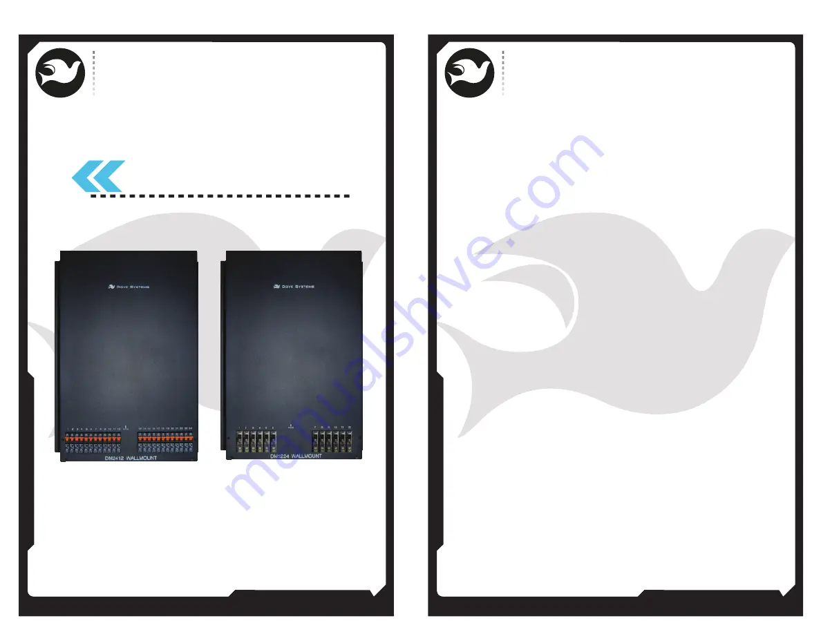
DM-1224, DM-2412

Digital Dimmer

Wallmount

OWNER’S MANUAL

805.541.8292\\805.541.8293

DOVE LIGHTING SYSTEMS INC.

\\3563 SUELDO STREET UNIT E

SAN LUIS OBISPO\\ CA 93401

OWNER’S MANUAL

02\\

01\\

Summary of Contents for DM-1224

Page 1: ...SYSTEMS INC 3563 SUELDO STREET UNIT E SAN LUIS OBISPO CA 93401 DM 1224 DM 2412 Digital Dimmer Wallmount OWNER S MANUAL 805 541 8292 805 541 8293 DOVE LIGHTING SYSTEMS INC 3563 SUELDO STREET UNIT E SAN LUIS OBISPO CA 93401 OWNER S MANUAL 02 01 ...

Page 2: ...ire 28 800 120 or 240 amps total power when all channels are at full This is available from a three phase 4 wire 80 amp or a single phase 3 wire 120 amp service Usually this much power is not required and a 40 60 amp service may be used with lower power loads plugged in The Dimmermaster accepts either three phase or single phase power input and is factory configured for three phase Line to neutral...

Page 3: ...nt case to earth ground often through a properly grounded conduit system This is not the same as the neutral or common and must not be confused with them The neutral is a separate load carrying circuit conductor The ground conductor should not normally carry current When the Dimmermaster is connected to its power source by conduit the ground connection can be made via the conduit itself If flexibl...

Page 4: ...he entire pack of twenty four dimmers If for example the starting dimmer number is 25 the pack reads control signals for channels 25 through 48 When the first digit of the thumbwheel switch reads 6 the pack is in load testing mode The second and third digits show the dimmer being tested from 1 to 24 The load test forces the output of the dimmer to full This is helpful for focusing and troubleshoot...

Page 5: ...inding module to heat sink and replace module 5 Reassemble in reverse order of disassembly 7 To change the circuit card 1 Disconnect power from dimmer 2 Remove front panel see above 3 Remove two screws and slide card out Set jumpers and switches on replacement card to match 4 Slide replacement card in until it seats into edge connector and screw down TROUBLESHOOTING CHART SYMPTOM No channels work ...

Page 6: ...ot responsible for damage to its apparatus through improper installation physical damage or poor operating practice If any device is found unsatisfactory under the warranty the buyer should notify the manufacturer and after receipt of shipping advice buyer may return it directly to Dove Systems San Luis Obispo CA shipping prepaid Such equipment will be replaced or put in proper operating condition...

Reviews: