background image

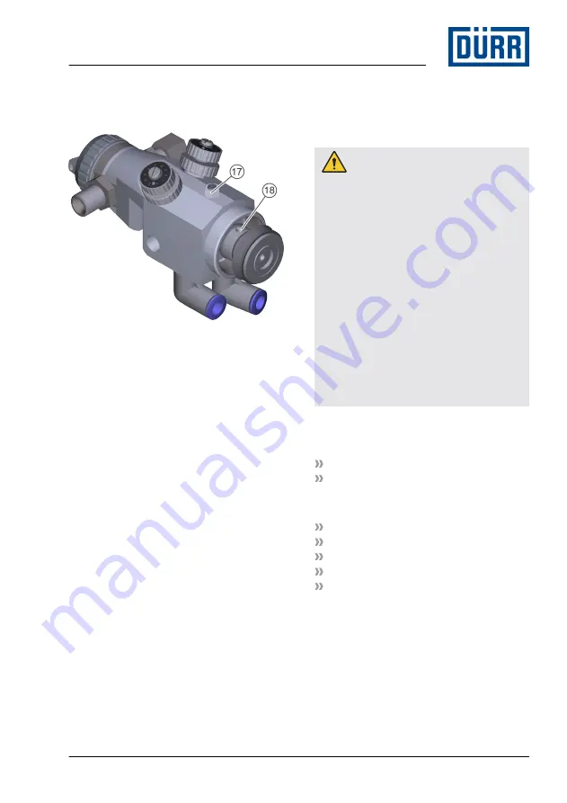
22. Lubricate piston sleeve and piston glide 

surface in the housing lightly with sili-

cone-free oil.

Fig. 26: Insert piston axis

23. Ensure that the tapering bore of the 

piston axis (18) is perpendicular to the 

tapped hole (17) in the housing.

24. Push in complete piston axis from 

behind into the housing.

25. Thread in the screw (2).

26. Screw on hex nut (1) and tighten it.

27. Lubricate needle shank lightly with sili-

cone-free oil. Push in needle (4) care-

fully into the housing from the back.

28. Insert needle spring (5) and plunger 

spring (6).

29. Fit end cap (7).

30. Fit cap nut (8). Tighten by hand.

10 

Disassembly and Disposal

10.1  Safety recommendations

 WARNING!

Material escaping under pressure

Material leaking under high pressure can 

penetrate the body. Even if the injury looks 

like a harmless cut wound, the penetrating 

material leads to amputation, serious inju-

ries can cause death.
– Do not try to seal leakages using body 

parts, gloves or towels.

– If there are injuries, seek medical 

attention immediately.

Before working on the product:
– Disconnect the system, in which the 

product is installed, from compressed 

air and material supply.

– Secure the system against being 

switched on again.

– Depressurize the lines.

10.2  Disassembly

Personnel:

Operator
 + additional qualification explosion pro-
tection

Protective equipment:

Use ear protection
Eye protection
Respiratory protection device
Protective workwear
Protective gloves

1. Rinsing 

Ä

 6.4 “Rinsing”.

2. Disconnect the compressed air supply 

and material feed. Secure against recon-

nection.

Disassembly and Disposal

02/2020

EcoGun AA AUTO - MSG00008EN

27/48

Summary of Contents for EcoGun AA AUTO

Page 1: ...EcoGun AA AUTO Automatic Spray Gun Air Assist MSG00008EN V04 N36230001V www durr com Operation manual ...

Page 2: ...e documentation Always follow safety instructions han dling instructions and specifications of every kind Illustrations can deviate from the tech nical construction Validity range of the document This document describes the following product N36230001V EcoGun AA AUTO Hotline and Contact If you have queries or would like technical information please contact your dealer or sales partner 02 2020 EcoG...

Page 3: ...2 Cleaning 16 8 Maintenance 17 8 1 Safety notes 17 8 2 Maintenance schedule 18 8 3 Lubrication 18 9 Faults 18 9 1 Safety recommendations 18 9 2 Defects table 20 9 3 Troubleshooting 22 9 3 1 Replace nozzle 22 9 3 2 Replace needle and seals 23 9 3 3 Replace needle spring and plunger spring 24 9 3 4 Set delay time 25 9 3 5 Replace piston seals 26 10 Disassembly and Disposal 27 10 1 Safety recommendat...

Page 4: ...ter depending on the requirement The following factors influence the spray jet and therefore the result Alignment of the air cap The alignment of the air cap determines the alignment of the spray jet Atomizer air pressure The higher the atomizer air pressure the finer is the atomization and the smaller is the spray pattern Horn air pressure The higher the horn air pressure the softer the spray jet...

Page 5: ...ormation and recom mendations 2 2 Intended Use Use The EcoGun AA AUTO spray gun is only intended for use in industry and craftman ship The EcoGun AA AUTO spray gun is solely intended for automatic coating of surfaces by one of the following operating methods As independent not hand guided device As part of a fully automated paint booth As part of a paint robot The material is fed through a high pr...

Page 6: ...nowledge Technical Measures for occupational safety and health The operator is responsible for the following work Operate and monitor the system product Introduce measures in the event of faults Clean system product additional qualification explosion pro tection In addition to the knowledge of the various specialist fields the mechanic has knowl edge of regulations and safety measures when working...

Page 7: ...s seek medical atten tion immediately Before working on the product Purge the system in which the product is installed Disconnect the system in which the product is installed from compressed air and material supply Depressurize the lines Secure the system against being switched on again Movable components There is a risk of death if components or equipment in the vicinity move unexpectedly Switch ...

Page 8: ...ray gun must be interrupted and secured against reconnection Lines seals and screw connections must be designed to conform to the require ments of the spray gun Ä 11 5 Operating values A support bracket capable of securing the spray gun is required The control air supply must be adjustable The control air supply must have venting The material must be fed through a filter to avoid clogging of the n...

Page 9: ...is non conduc tive or is not grounded Ensure housing contact Resistance between housing and grounding terminal 1MΩ Fig 3 Connect 4 The spray gun does not work when the lines are not connected correctly Connect lines Ensure correct assign ment 1 Material M 2 Spraying air A 3 Control air C Connect lines to both material connections for paint circulation mode For tap line mode connect line to a mater...

Page 10: ...ion Attach spray gun on the support bracket as for the stationary assembly and ground it properly Ä Stationary assembly Fig 4 Assembling robot accessories 2 Lock spraying air connection A with the blind plugs of the robot kits 4 3 Replace regulating inserts of the atomizer air control R and the horn air control F by the regulating inserts and the screw in plug connections of the robot kits 1 and 2...

Page 11: ... tection Protective equipment Use ear protection Eye protection Respiratory protection device Protective workwear Protective gloves Depending on the design of the application system two technicians must be present to execute the commissioning Technician 1 Operates the controls Technician 2 Check on the spray gun 1 Actuate the spray gun without material via the control unit or the visualizer 2 Chec...

Page 12: ...pply R and horn air supply F completely If horn air and atomizer air are blocked atomization is done exclusively through material pres sure airless mode 2 Adjust material quantity by means of the nozzle size Adjust material pressure air through valves in the control cabinet Observe the following character istic curve Fig 8 Rectify the offshoot 3 Open horn air control 2 or horn air supply F until t...

Page 13: ...e product that can harm components Rinse product immediately after each use 6 2 General notes 1 Perform the following checks during oper ation Check O rings for correct seating and tightness Check air car for cleanliness Check nozzle for cleanliness 6 3 Selecting air cap You can convert the spray gun for various uses by swapping the air cap Air cap for hexagonal nozzle The air cap for hexagonal no...

Page 14: ...propriate rinsing agent until the rinsing agent runs clean without any material residue 7 Cleaning 7 1 Safety recommendations WARNING Danger of fire and explosion Flammable coating materials and their detergents and cleaning agents can cause a fire or an explosion Ensure that the flashpoint of the fluid is at least 15 K above the ambient tem perature Note explosion group of the fluid Follow the sa...

Page 15: ... agents and cleaning agents that do not contain any halo genated hydrocarbons NOTICE Unsuitable cleaning agents Unsuitable cleaning agents can damage the product Only use cleaning agents approved by the material manufacturer Follow safety data sheets Place heavily soiled components in a cleaning bath Only place those parts in the cleaning bath which are suitable for the cleaning bath Use only elec...

Page 16: ...ou can remove the air cap and the nozzle Disassembly 1 Loosen the cap nut 3 and remove it 2 Remove air cap 1 and nozzle 3 Push out nozzle 2 from the back of the air cap and catch it 4 Clean air cap using cleaning agent and cleaning brush Ä 12 2 Tools 5 Wipe the cleaned air cap dry with a cloth 6 Clean the nozzle in the cleaning bath Assembly Fig 12 Insert nozzle 7 Insert nozzle 2 from the back to ...

Page 17: ...ct e g with eyes skin WARNING Material escaping under pressure Material leaking under high pressure can penetrate the body Even if the injury looks like a harmless cut wound the penetrating material leads to amputation serious inju ries can cause death Do not try to seal leakages using body parts gloves or towels If there are injuries seek medical attention immediately Before working on the produc...

Page 18: ...tion explosion pro tection Protective equipment Protective workwear Protective gloves Piston axis needle shank piston sleeve and piston glide surface in the gun housing must be lubricated so that there will not be any leakages Fig 13 Lubricate piston components 1 Feed lubricant silicone free oil at the control air connection C 1 using con trol air 9 Faults 9 1 Safety recommendations CAUTION Risk o...

Page 19: ...ty damage due to improper han dling Mechanical load can damage needle and nozzle Handle with care during installation and dismantling Do not subject the needle to any mechanical pressure Avoid collisions of components to be assembled and disassembled with the needle Do not excessively tighten compo nents NOTICE Improper setting causes damage The delay time is factory set Setting a wrong delay time...

Page 20: ...ive together with the seal retainer screw Ä 9 3 2 Replace needle and seals Needle spring and plunger spring are worn out Replace needle spring and plunger spring Ä 9 3 3 Replace needle spring and plunger spring Seal retainer screw seal washer or needle is worn out Replace seal retainer screw seal washer and needle Ä 9 3 2 Replace needle and seals Material escapes at the needle seal Needle seal is ...

Page 21: ...oiled or defec tive Clean and check the nozzle Replace nozzle if defective Ä 9 3 1 Replace nozzle Material pressure is too low Increase material pressure Feed line is pinched or broken Check infeed line Needle does not close correctly Check Control air Check operation of needle Replace needle if defective together with the seal retainer screw Ä 9 3 2 Replace needle and seals Cap nut is not correct...

Page 22: ...ove air cap 1 and nozzle 3 Push out nozzle 2 from the back of the air cap and catch it Fig 15 Check seal 4 Check seal 4 for damage 5 Replace worn out or defective compo nents Assembly Fig 16 Insert nozzle 6 Insert nozzle 2 from the back to fit into the air cap 1 Pay attention to the cor rect alignment of the nozzle groove 5 7 Fit air cap 1 and nozzle 8 Align air cap 9 Fit cap nut 3 Tighten by hand...

Page 23: ...eedle spring 2 and plunger spring 3 4 Pull back complete needle 1 out of the housing Fig 18 Disassemble air cap seal retainer screw and sealing ring 5 Loosen the cap nut 9 and remove it 6 Remove air cap 8 and nozzle 7 Unscrew and remove seal retainer screw with sealing washer 7 using a socket wrench 10mm 8 Remove sealing ring 6 Fig 19 Disassemble needle seal 9 Unscrew custom nut 11 using an open e...

Page 24: ...asher 7 Tightening torque 18 to 20Nm 20 Fit air cap 8 and nozzle 21 Align air cap 22 Fit cap nut 9 Tighten by hand 23 Lubricate needle shank lightly with sili cone free oil Push in needle 1 care fully into the housing from the back 24 Insert needle spring 2 and plunger spring 3 25 Fit end cap 4 26 Fit cap nut 5 Tighten by hand 27 Tighten needle gland 12 sensitively 9 3 3 Replace needle spring and ...

Page 25: ...ap 6 3 Remove needle spring 4 and plunger spring 5 4 Loosen guide nut 3 Setting Fig 23 Adjust distance from piston holder to pre air stop nut 5 Rotate pre air stop nut 2 Turn it to the right to reduce the delay time Turn it to the left to increase the delay time The recommended distance from the pre air stop nut 2 to the piston holder 1 is about 1 5mm If a longer delay is needed increase the dista...

Page 26: ...nut 9 9 Pull out sealing body 10 from piston axis 16 10 Pull off stop bush 11 11 Pull off ball bearing plate springs 12 12 Loosen bracket nut 13 13 Pull off counter washer 14 14 Pull off piston sleeve 15 15 Replace seals of the stop bush 11 sealing body 10 and piston sleeve 15 Worn out sealing rings which are inside of the stop bush need to be replaced by Dürr Systems Assembly 16 Use a drop of oil...

Page 27: ...leaking under high pressure can penetrate the body Even if the injury looks like a harmless cut wound the penetrating material leads to amputation serious inju ries can cause death Do not try to seal leakages using body parts gloves or towels If there are injuries seek medical attention immediately Before working on the product Disconnect the system in which the product is installed from compresse...

Page 28: ...ing to the disposal provisions in force In case of doubt refer to the local dis posal authorities 11 Technical data 11 1 Dimensions and weight Fig 27 Dimensions Detail Value Length 150mm Width 70mm Height 90mm Weight 670g Nozzle diameter 0 18 to 0 7mm 11 2 Connections Connection Nominal width Material 2x G1 4 thread Control air and spraying air ver sion dependent Control air Ø 6mm or Ø 4mm or Ø 1 ...

Page 29: ...atures the following details Product designation Material number Year of manufacture Serial number EX labelling Manufacturer CE labelling 11 7 Materials used Component Material Housing Nickel plated alu minum Cap nut Aluminum Compression springs Stainless steel Materials in contact with material Stainless steel Seals in contact with material PTFE FEPM Seals without mate rial contact NBR 11 8 Opera...

Page 30: ...ig 28 Exploded view Klüber Syntheso GLEP 1 Item Denomination Quan tity Material number 1 Lip seal 5 0 x 9 0 x 2 9 1 Ä Spare part sets 2 Locknut 1 M67010085 3 Sealing body 1 4 Piston axis 1 Replacement parts tools and accessories 02 2020 EcoGun AA AUTO MSG00008EN 30 48 ...

Page 31: ...0241 18 End cap 1 M25010070 19 Cap nut 1 M30010317 20 Cap nut with seal 1 M30010385 21 Air cap 1 Ä Overview Air caps and nozzles 22 Seal 1 M08280049 23 Nozzle 1 Ä Overview Air caps and nozzles 24 Seal retainer screw with sealing washer 1 M41060166 25 Sealing ring 1 M08010529 26 Connecting piece 1 M01010205 27 Double nipple 2 M56100470 28 O ring 4 0 x 1 2 4 Ä Spare part sets 29 Control screw 2 M579...

Page 32: ... Elbow spraying air A 1 M57310089 Ø 8 or M55170052 Ø 3 8 38 Elbow control air C 1 M55170053 Ø 6 or M57310085 Ø 4 or M55170051 Ø 1 4 Fig 29 Exploded view robot version Item Denomination Quan tity Material number 39 Elbow plug in connection 2 Ä 12 3 Accessories 40 Regulator insert 2 41 Sealing screw 1 4 1 Replacement parts tools and accessories 02 2020 EcoGun AA AUTO MSG00008EN 32 48 ...

Page 33: ...rsion only with horn air connection Item Denomination Quan tity Material number 42 Sealing screw 1 M41090197 43 Throttle factory set 1 M57930028 Replacement parts tools and accessories 02 2020 EcoGun AA AUTO MSG00008EN 33 48 ...

Page 34: ...rew 1 M41090197 Overview Air caps and nozzles Nozzle labeling example 411 428 VZ 4 Spray jet angle examples 1 10 2 20 3 30 4 40 etc 11 Nozzle size in inches examples 07 0 007inch 09 0 009inch 11 0 011inch etc 28 Nozzle size in mm example 18 0 18mm 23 0 23mm 28 0 28mm etc VZ With pre atomizer Replacement parts tools and accessories 02 2020 EcoGun AA AUTO MSG00008EN 34 48 ...

Page 35: ...25 M09020381 0 28 0 011 10 51 to 76 0 37 M09020382 0 28 0 011 20 102 to 152 0 37 M09020383 0 28 0 011 30 152 to 203 0 37 M09020384 0 28 0 011 40 203 to 254 0 37 M09020385 0 28 0 011 50 254 to 305 0 37 M09020386 0 28 0 011 60 305 to 356 0 37 M09020387 0 28 0 011 70 356 to 406 0 37 M09020388 0 33 0 013 10 51 to 76 0 57 M09020389 0 33 0 013 20 102 to 152 0 57 M09020390 0 33 0 013 30 152 to 203 0 57 M...

Page 36: ...to 203 0 98 M09020408 0 43 0 017 40 203 to 254 0 98 M09020409 0 43 0 017 50 254 to 305 0 98 M09020410 0 43 0 017 60 305 to 356 0 98 M09020411 0 43 0 017 70 356 to 406 0 98 M09020412 0 43 0 017 80 406 to 457 0 98 M09020413 0 43 0 017 90 457 to 508 0 98 M09020414 0 48 0 019 10 51 to 76 1 30 M09020415 0 48 0 019 20 102 to 152 1 30 M09020416 0 48 0 019 30 152 to 203 1 30 M09020417 0 48 0 019 40 203 to...

Page 37: ... 0 60 0 024 30 152 to 203 1 95 M09020435 0 60 0 024 40 203 to 254 1 95 M09020436 0 60 0 024 50 254 to 305 1 95 M09020437 0 60 0 024 60 305 to 356 1 95 M09020438 0 60 0 024 70 356 to 406 1 95 M09020439 0 60 0 024 80 406 to 457 1 95 M09020440 0 60 0 024 90 457 to 508 1 95 M09020441 0 70 0 028 10 51 to 76 2 70 M09020442 0 70 0 028 20 102 to 152 2 70 M09020443 0 70 0 028 30 152 to 203 2 70 M09020444 0...

Page 38: ...0732 0 23 0 009 20 102 to 152 0 25 M09020685 0 23 0 009 30 152 to 203 0 25 M09020691 0 23 0 009 40 203 to 254 0 25 M09020697 0 23 0 009 50 254 to 305 0 25 M09020717 0 23 0 009 60 305 to 356 0 25 M09020702 0 28 0 011 20 102 to 152 0 37 M09020686 0 28 0 011 30 152 to 203 0 37 M09020692 0 28 0 011 40 203 to 254 0 37 M09020698 0 28 0 011 50 254 to 305 0 37 M09020718 0 28 0 011 60 305 to 356 0 37 M0902...

Page 39: ...to 254 0 98 M09020701 0 43 0 017 50 254 to 305 0 98 M09020722 0 43 0 017 60 305 to 356 0 98 M09020707 0 43 0 017 70 356 to 406 0 98 M09020736 0 43 0 017 80 406 to 457 0 98 M09020746 0 43 0 017 90 457 to 508 0 98 M09020714 0 48 0 019 30 152 to 203 1 30 M09020733 0 48 0 019 40 203 to 254 1 30 M09020734 0 48 0 019 50 254 to 305 1 30 M09020735 0 48 0 019 60 305 to 356 1 30 M09020708 0 48 0 019 70 356 ...

Page 40: ...at 100bar pressure with water 3 Use the following formula for calculating flow rate Q2 for new operating pressure P2 Q2 Q1 P2 P1 P1 100bar Q1 flow rate according to table Air caps Air cap Item Material number Air cap for hexagonal nozzles 10 to 30 21 22 M35030077 Air cap for hexagonal nozzles 40 to 130 M35030078 Air cap for circular nozzles M35030229 Spare part sets Seal set M08220022 Denomination...

Page 41: ...50035 is required for disassembling a worn out lip seal In addition a contact adhe sive cyanacrylate is required for assembly Repair kit N36960099 Denomination Item Quantity Lip seal 5 0 x 9 0 x 2 9 1 1 Locknut 2 1 Sealing body 3 1 Sealing ring 5 2 O ring 16 0 x 2 0 7 2 Piston sleeve 11 1 Needle 13 1 Seal retainer screw with sealing washer 24 1 Sealing ring 25 3 O ring 4 0 x 1 2 28 8 Sealing washe...

Page 42: ...eedle set N36960132 Denomination Item Quantity Needle 13 1 Seal retainer screw with sealing washer 24 1 Sealing ring 25 1 Piston axis complete pre assembled M67010085 Denomination Item Quantity Locknut 2 1 Sealing body 3 1 Piston axis 4 1 Sealing ring 5 2 Stop bush 6 1 O ring 16 0 x 2 0 7 2 Ball bearing plate spring 8 6 Bracket nut 9 1 Counter washer 10 1 Piston sleeve 11 1 Piston holder 12 1 Repl...

Page 43: ...sories A complete overview of the accessories is available from the Dürr Webshop Denomination Item Quan tity Material number Flexible protective sleeve for spray gun 1 W20910224 Color tube with filter G1 4 1 M34040020 90 elbow union G1 4 1 4 NPSM in stainless steel adjustable 1 M55030173 90 elbow union G1 4 G1 4 in stainless steel adjustable 1 M55030171 Support bracket for stand tube Ø 26 1 N66030...

Page 44: ...ion for air hose Ø 8 39 2 M57310090 Regulator insert 40 2 Sealing screw 1 4 41 1 Robot kit US N36960142 Denomination Item Quan tity Material number Elbow plug in connection for air hose Ø 3 8 39 2 M55170054 Regulator insert 40 2 Sealing screw 1 4 41 1 Cleaning set Denomination Item Quan tity Material number Cleaning set 21 parts 1 N36960038 Cleaning needles 33mm 0 011 to 0 017 12 pcs 1 W33130004 C...

Page 45: ...iginal replacement parts WARNING Unsuitable replacement parts Replacement parts of third party suppliers may possibly not be able to hold the loads Serious injury and death could be the con sequence Use exclusively original replacement parts Ordering replacement parts tools and accessories as well as information on prod ucts that are listed without order number Ä Hotline and Contact Replacement pa...

Page 46: ...02 2020 EcoGun AA AUTO MSG00008EN 46 48 ...

Page 47: ...02 2020 EcoGun AA AUTO MSG00008EN 47 48 ...

Page 48: ...n Germany www durr com Phone 49 7142 78 0 The reproduction and distribution of this document use and communication of its contents are not permitted without express written approval Offenders will be liable for damages All rights reserved in the event of the grant of a patent or utility model Dürr Systems AG 2015 www durr com ...

Reviews: