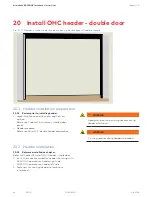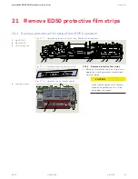
50
ED50
08-2018
DL4614-140
dormakaba ED50 OHC Installation Instructions
Chapter 24
24 Install ED50 OHC operators and
hardware; double door header
24.1 Install ED50 operators in header
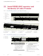
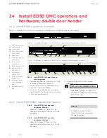
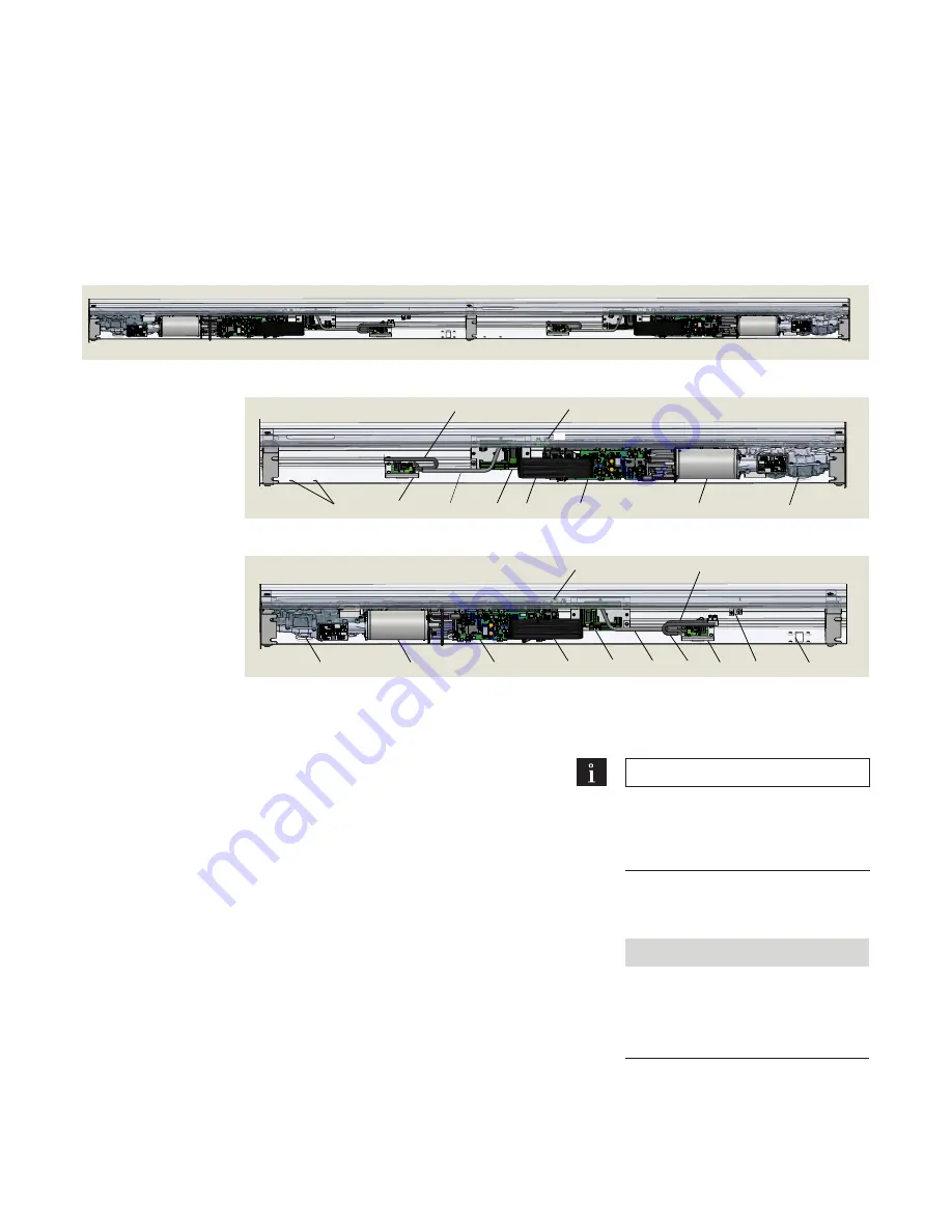
Fig.24.1.1 Header with ED50 OHC operators and hardware installed, double egress example
4
2
1.1
1
5
3
7
9
1.2
1.3
Fig.24.1.2 Header RH door with ED50 OHC operator and hardware installed
1
ED50 OHC operator
1.1
Control board
1.2
Output shaft
1.3
ED50 OHC operator
115 VAC cable
2
Ribbon cable
3
Low voltage terminal
board module
4
115 Vac power
extension cable
5
115 Vac power module
5.1
Main power cable
DK3772-010
6
Ground lug kit
DK4656-010
7
7
115 Vac power cable
DX3484-030
8
Mounting holes and
cutout, breakaway
switch
9
Mounting holes, fixed
stop
1
1.2
1.1
2
3
4
5
7
5.1
6
8
1.3
Fig.24.1.3 Header LH door with ED50 OHC operator and hardware installed
24.1.1 Install ED50 OHC operators on
mounting plate.
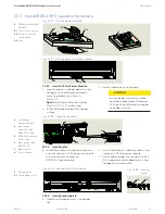
1. Operator protective film strips must be
removed! Reference Chapter 21.
2. Install two ED50 OHC operators onto
onto their mounting plates.
3. Use 5 mm T handle hex key to thread
eight M6 SHCS into their mounting plate
holes for each operator.
4. Tighten all eight M6 SHCS on each
operator.
TIPS AND RECOMMENDATIONS
Reference Chapter 17, Para. 17.1
for detail on operator to mounting
plate fastening.
24.2 Install ED50 OHC operator hardware
24.2.1 Install ED50 OHC operator
hardware, RH door
1. Refer to Chapter 23, Para. 22.4 for
hardware installation steps for RH side
of header.
NOTICE
Installation of ground lug kit
(Para. 23.4.3) is not required on
RH side of header.
24.2.2 Install ED50 OHC operator
hardware, LH door
1. Refer to Chapter 22, Para. 21.4 for
hardware installation steps for LH side
of header.

