background image

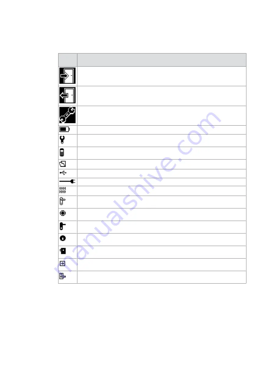
3.1.2 Display symbols

In each menu, the display shows various symbols or moving symbols for the user's
information.
The most important symbols are explained below.

Sym-
bols

Meaning/Function

Export menu

Import menu

Settings menu

Battery charge status

Settings

Programmer

Data

USB connected

Connect to programmer

Firmware

General symbol for actuators

Digital cylinder

c-lever

Cylinder

Locker lock

Reader

c-lever compact

3.2 Scope of delivery

1 USB cable (for programming and configuration)

1 mains adapter

1 quick guide

Product description

User Manual

10

- 06/2021

dormakaba Programmer 1460

Summary of Contents for 1460

Page 1: ...EN User Manual dormakaba Programmer 1460 06 2021 ...

Page 2: ...1 3 Navigation buttons and ENTER 12 4 1 4 Alphanumeric buttons 13 4 1 5 Home button 13 4 2 Switching on the programmer 13 4 3 Display dialogues 13 4 4 Wireless programming 14 4 5 Settings 14 4 5 1 Programmer settings 14 4 5 2 Actuator settings 19 4 5 3 Data settings 25 5 Programming 27 5 1 Setting the properties and functions of a component 27 5 2 System level 27 5 3 Export to components 29 5 3 1 ...

Page 3: ...rom the system software 41 6 3 Set clock 41 7 Maintenance 42 7 1 Battery charge status 42 7 2 Charging the battery 42 7 3 Menu structure 43 8 Service 44 8 1 EAC Service Tool 44 8 1 1 Programmer 1364 updating firmware 45 8 1 2 Programmer 1460 updating firmware 45 8 1 3 Actuators updating firmware 45 8 1 4 Updating desktop reader 91 08 46 8 1 5 Creating a programmer memory image 47 8 2 Emergency sup...

Page 4: ...rying out these activities and to minimise these risks as far as possible It is the skilled person s responsibility to ensure that the conditions stated by the manufacturer and the applicable regulations and standards are complied with when carrying out these actions This documentation is also used to provide information for persons with the following tasks Project planning and project implementat...

Page 5: ...akaba c lever dormakaba c lever compact dormakaba c lever pro dormakaba c lever air Cabinet lock dormakaba cabinet Lock 21 10 Wireless Reader dormakaba remote reader 91 15 E320 with wireless extension module 90 43 Desktop reader dormakaba desktop reader 91 08 Programmer 1364 dormakaba Programmer 1364 Programmer 1460 dormakaba Programmer 1460 KEM dormakaba evolo Manager EST dormakaba EAC Service To...

Page 6: ...tion which may lead to minor physical injury NOTICE Important information on the correct use of the product Failure to comply with these instructions could lead to malfunctions It is possible to damage the product The warning information for the highest level in each case is always used when several hazard levels occur at the same time If warning information warns about personal injury the same pi...

Page 7: ...y information The following safety instructions must be followed for safe use of the device CAUTION The electronic device must be protected from the following external influences direct sunlight direct heat sources such as heating direct fluids such as water temperature fluctuations e g below 0 C 2 3 Service and maintenance Conversions and modifications to the product may only be done skilled pers...

Page 8: ...inted earthed metal component This way static discharges are channelled away from your body safely and effectively Handle a PCB along its edges only Do not touch the PCB or connectors Place dismantled components on an anti static surface or in an anti static shielded con tainer Avoid contact between PCBs and clothing The wrist strap protects PCBs against an elec trostatic discharge voltage from th...

Page 9: ...he same time the programmer is the link interface between the system software and the components 3 1 1 Layout Programmer 1460 1 1 Radio interface 2 Programming cable connector 3 Display 4 Menu buttons 5 UP navigation button 6 ENTER 7 DOWN navigation button 8 Alphanumeric buttons 9 ON OFF button 10 Home Cancel Back 11 USB interface main charger con nector Product description User Manual 9 06 2021 d...

Page 10: ...ort menu Import menu Settings menu Battery charge status Settings Programmer Data USB connected Connect to programmer Firmware General symbol for actuators Digital cylinder c lever Cylinder Locker lock Reader c lever compact 3 2 Scope of delivery 1 USB cable for programming and configuration 1 mains adapter 1 quick guide Product description User Manual 10 06 2021 dormakaba Programmer 1460 ...

Page 11: ...le Cable linked connection with the components USB USB interface for PC connec tion Data transfer from and to system software Memory capacity internal SD card Sites authorisations trace back Approx 500 data records can be stored per master key sys tem Ambient conditions Protection type IP40 Temperature 0 50 C Humidity 0 95 RH non condensing 3 4 Conformity This product conforms to the EU directives...

Page 12: ... Chapter 4 5 1 10 4 1 2 Menu buttons The programmer is operated using the keypad The three menu buttons under the display are directly related to the display Every button is assigned a menu Additional button functions are displayed in the dialogues on the display e g for making decisions 4 1 3 Navigation buttons and ENTER The three buttons under the menu buttons are the two navigation buttons UP u...

Page 13: ...orrect PIN is input 6 times in succession the PIN and the locking plans on the programmer are deleted Further information on PIN protection can be found in the Chapter 4 5 1 10 1 Press the ON OFF button for about two seconds The main menu is opened 4 3 Display dialogues During operation the display shows a number of different dialogues with prompts and messages 1 Watch the display carefully during...

Page 14: ...ust be held with its front pointing directly at the component antenna Example c lever 4 5 Settings Different properties and settings can be adjusted in the Settings menu Actuators Data Programmer Firmware update Emergency power supply 4 5 1 Programmer settings 1 Press the Settings menu key 2 Use the navigation keys to select the Programmer menu 3 Press the ENTER key ð The properties are displayed ...

Page 15: ...Open the Programmer menu 3 Choose the Contrast sub menu 4 Press the ENTER key 5 Select the desired contrast value using the navigation keys 6 Press the ENTER key ð The value is saved 4 5 1 3 Setting the volume 1 Open the Settings menu 2 Open the Programmer menu 3 Choose the Volume sub menu 4 Press the ENTER key 5 Select the volume level using the navigation keys 6 Press the ENTER key Note The valu...

Page 16: ... active position 5 Enter the current date and time using the alphanumeric keys Note Change the positions of the cursor using the navigation keys 6 Press the ENTER key ð The current values are saved 4 5 1 5 Setting the lighting 1 Open the Settings menu 2 Open the Programmer menu 3 Choose the Lighting sub menu 4 Press the ENTER key 5 Select the lighting variant 6 Press the ENTER key ð The selection ...

Page 17: ...n is saved 4 5 1 7 Setting the switch off time Setting the optimum switch off time enables the power consumption of the programmer to be reduced and operation until the battery next requires charging to be prolonged 1 Open the Settings menu 2 Open the Programmer menu 3 Select the Switch off time sub menu 4 Press the ENTER key 5 Select the switch off time 6 Press the ENTER key ð The selection is sa...

Page 18: ...r for protection from unauthorised use There is a prompt for the PIN upon switching on the Programmer The PIN does not have to be input any more until the Programmer is switched off If a PIN has been set up through the system software it is overwritten by the PIN set up with the menu A PIN that has been set up through the menu of the Programmer cannot be changed by the system software The PIN can ...

Page 19: ...hether the traceback of the component should be downloaded Configuration menu 1 Open the Settings menu 2 Open the Programmer menu 3 Open the Comfort update menu 4 Select the Configuration sub menu Select The user decides whether the existing configuration of a component should be preferred over a configuration saved in the programmer Prefer internal The configuration of the component saved in the ...

Page 20: ...7 Select Yes ð The time is updated 4 5 2 2 Battery change In this menu a time stamp is created for the battery change 1 Open the Settings menu 2 Open the Actuator menu 3 Log in to the actuator using the master medium 4 Connect the programmer to the actuator 5 Select the Battery change sub menu 6 Press the ENTER key 7 Select Yes if a new battery has been placed Operation User Manual 20 06 2021 dorm...

Page 21: ...f 8 Press the ENTER key ð The selection is saved 4 5 2 4 Light signal This functions can only be applied for actuators with LED and illumination unit 1 Open the Settings menu 2 Open the Actuator menu 3 Log the master medium in to the actuator 4 Connect the programmer to the actuator 5 Choose the Illumination unit sub menu 6 Press the ENTER key 7 Select On or Off 8 Press the ENTER key ð The selecti...

Page 22: ...rised sub menu 6 Press the ENTER key 7 Select On or Off 8 Press the ENTER key ð The selection is saved 4 5 2 6 Opening time The opening time determines the duration for which the actuator remains coupled for actuation 1 Open the Settings menu 2 Open the Actuator menu 3 Log the master medium in to the actuator 4 Connect the programmer to the actuator 5 Select the Opening time sub menu 6 Press the E...

Page 23: ... the Actuator menu 4 Log the master medium in to the actuator 5 Choose the Actuator TouchGo selectivity sub menu 6 Press the ENTER key 7 Select a value between 1 and 6 Note Value 1 corresponds to the lowest sensitivity The factory setting is 3 8 Press the ENTER key ð The selection is saved 4 5 2 8 INI reset 1 Open the Settings menu 2 Open the Actuator menu 3 Log the master medium in to the actuato...

Page 24: ...the ENTER key The following options are available in the Wireless menu Connect to the network Disconnect from the network Display status of the network Procedure for connecting to the network 1 Choose Connect 2 Confirm with ENTER ð Search for network Network is searched for ð Gateway GW found ð Connecting to the GW is executed ð Putting into operation ð Connected to GW ð The linked actuator is con...

Page 25: ...he plan for this component are saved in the programmer arrow or if the component has been completely configured 4 5 3 2 Actuator firmware ü The most up to date firmware version has been downloaded from the EAC Service Tool 8 1 1 Open the Data settings menu 2 Select the Actuator firmware sub menu 3 Press the ENTER button ð All variants of the actuator technology stored on the programmer are display...

Page 26: ...settings menu 2 Select the Delete all sub menu 3 Press the ENTER button 4 Select Yes ð All data is deleted from the programmer 4 5 3 5 Delete all key plans All key plans are deleted from the programmer in this menu 1 Open the Data settings menu 2 Select the Delete all key plans sub menu 3 Press the ENTER button 4 Select Yes ð All key plans are deleted from the programmer Operation User Manual 26 0...

Page 27: ...system level Depending on the system level that is set the component has a certain scope of functions The host systems provide the parameter settings for the system level assigned to them It is then not possible to set parameters for a component with the incorrect system level Overview Overview of the host systems used and the matched system level System System level Definition on the Programmer F...

Page 28: ...ogrammer 1460 1 26 The Programmer compares the system level of the parameter file with the system level of the component Component firm ware version 42 28 In the factory the system level is set according to the order Update to a higher system level The components are dispatched from the factory with a certain system level If certain functions are to be used which are not released in that system le...

Page 29: ... menu opens 2 Log the master in to the component Activate the electronics on cabinet lock 21 10 by pressing briefly on the door 3 Choose a key plan 4 Press the ENTER key 5 Choose an actuator 6 Press the ENTER key 5 3 2 Updating evolo components ü Valid master medium available 1 Press the Export menu key ð The Export menu opens 2 Log the master in to the component ð Update the configuration Activat...

Page 30: ...inder 4 Choose a key plan 5 Press the ENTER key 6 Choose an actuator 7 Press the ENTER key 5 3 4 Updating a mechatronics cylinder ü Valid master medium available ü Programming adapter and programming cable available 1 Press the Export menu key ð The Export menu opens 2 Insert the master into the mechatronic cylinder and remove it again 3 Insert the programming adapter into the mechatronic cylinder...

Page 31: ...software for evaluation with the Programmer 5 4 1 Info In this menu information about the components is displayed Log in to the component using a master medium in order to display all available information for this component Basic information is always displayed Type Actuator type Name Name of the actuator if input otherwise serial number of the actuator Tech technology Bat Battery status Clock Da...

Page 32: ...tem software operating manual 5 4 3 Diagnostic details The diagnosis data aid the support team in error analysis In this menu diagnosis data are read from the components The data can only be read if programmer and component are connected using the programming cable Before reading the diagnosis data delete all data on the programmer This helps the support team in carrying out an efficient data anal...

Page 33: ...onent configuration is read and confirmed 5 4 5 Import from mechatronics cylinder ü Valid master medium available ü Programming adapter and programming cable available 1 Press the Import menu key ð The Import menu opens 2 Insert the master into the mechatronic cylinder and remove it again 3 Insert the programming adapter into the mechatronic cylinder 4 Choose a menu e g Configuration 5 Press the E...

Page 34: ...terference The transponder is defective or not available The door handle is not being touched or the installation is deficient Increased interference within the en vironment Increased level of interference within the en vironment The transponder is not being carried correctly A weak signal is being received Deficient installation The transponder is not being carried correctly or its batteries are ...

Page 35: ...checked and if necessary the firmware of the Programmer must be updated The firmware update of OSS SO is carried out like the firmware update of V4 If there is already a configuration stored in the Programmer for this component it can be overwritten by the configuration from the component A connection of the component to a wireless gateway must be manually restored after the firmware update Requir...

Page 36: ...e 2 On the Programmer select the Firmware update menu ð All the firmware versions for the connected component are displayed 3 Select the firmware ð The update process is started ð The selected firmware is stored in the component ð The component is restarted with the new firmware ð The firmware update is completed 5 6 2 Crossgrade for LEGIC advant components An upgrade to E300 V4 is recommended for...

Page 37: ...e variants for the readers are shown in the following table The products can be used in various function types and system software The functions can differ in each function type The functional type is based on the firmware used as an online reader in the Access Manager functional type Kaba exos B COMM as an online reader in the Subterminal functional type B COMM or as a standalone reader in the St...

Page 38: ...2 c lever compact K6 Digital cylinder 2 Mechatronic cyl inder Forend 5 Mechatronic cyl inder Surface fixed Compact 2 Remote reader 3 Compact reader 3 Cabinet lock 21 10 2 Legend 1 Hold the master medium in front of it 2 Hold the master medium or authorised user medium in front of it difference before the INI reset for V4 and during the INI reset for V3 3 Set DIP switch 6 to ON 4 Not for V3 compone...

Page 39: ...ium to perform an INI reset Actuators Tweezers DIP switch c lever c lever compact 5 digital cylinder 5 Mechatronic cyl inder 5 Remote reader 7 6 compact reader 7 6 Legend 5 Hold the master medium or authorised user medium in front of it difference For V4 be fore the INI reset or for V3 during the INI reset 6 Set DIP switch 5 6 to ON 7 Not for online actuators Reset information for other actuators ...

Page 40: ...Main memory 1 GB 2 GB recommended Hard drive memory min 50 MB including all additional components Interface 1 x USB 2 0 Supported operating systems Windows 10 32 64 bit Windows 8 or 8 1 Windows 7 Windows Server 2012 Windows Server 2008 Windows Server 2008 R2 Procedure 1 Download the installation package from the dormakaba website 2 Unpack the installation package 3 Open the installation package ð ...

Page 41: ... the associated actuator data from the system software to the programmer The system software procedure is described in the system software manual 5 Search for the actuators using the programmer 6 For how to transfer the data to the actuators see Chapter 5 3 6 3 Set clock Time on programmer To use the automatic clock setting on the programmer execute the following steps 1 Switch on the PC 2 Start t...

Page 42: ...PC The mains adapter is recommended for a complete charge cycle Charging the battery using the mains adapter 1 Connect the programmer to the mains adapter using the USB cable 2 Plug the mains adapter into a socket 3 The programmer switches on automatically 4 The programmer charges the battery by itself when it is connected to the mains adapter Charging the battery using the PC 1 Switch on the PC 2...

Page 43: ...ep unauthorized Opening times TouchGo selectivity INI reset Wireless Back Data Doors Actuator firmware Memory information Delete all Delete locking plans Back Programmer Language Contrast Volume Date Time Lighting Key sound Turn off time Name Information PIN protection Comfort update Back Firmware Update Firmware versions Back Emergency power supply Back Maintenance User Manual 43 06 2021 dormakab...

Page 44: ...d for transferring the firmware for the components to the programmer Desktop reader 91 08 LEGIC MIFARE MRD Wizard for updating the desktop reader firmware for the selec ted technology Programmer 1460 memory image Wizard for creating a ZIP file with the memory content of the programmer A tool for problem solving in support cases Actuator memory image V4 Wizard for creating a ZIP file with the memor...

Page 45: ...s 5 Select the current firmware file and confirm by selecting Next ð The programmer is updated 6 Click on the Finish button 8 1 3 Actuators updating firmware 1 Start the EAC Service Tool auxiliary program 2 Connect the programmer to the computer 3 Click on the Actuator firmware button 4 Follow the wizard s instructions 5 Select the current firmware file Note Files which are displayed as inactive a...

Page 46: ...ribed in the user manual for the programmer 1460 8 1 4 Updating desktop reader 91 08 1 Start the EAC Service Tool auxiliary program 2 Connect the desktop reader to the computer 3 Press the Desktop reader 91 08 selected technology button 4 Follow the wizard s instructions 5 Select the current firmware file 6 Click on the Next button ð The desktop reader is updated 7 Click on the Finish button Servi...

Page 47: ...ors can no longer be opened from the outside with the components All functions are blocked Only Batteries flat is indicated acoustic signal three seconds in duration The following actuators can still be opened with the programmer and emergency supply c lever TouchGo Behaviour of the actuators whilst the emergency supply is applied Actuators remain open Entry Emergency supply event written to trace...

Page 48: ...7 Replace the batteries 8 Check the function of the component Service User Manual 48 06 2021 dormakaba Programmer 1460 ...

Page 49: ...de No network No GW reachable or GW is not prepared for join At the ZigBee level there is no answer with an open for join upon a beacon re quest Check Gateway power supply Gateway settings Signal strength to from gateway Communication error If the PD is unplugged or the PD wireless con nection is lost a communication error and then Connection disconnected is displayed Try again Connection discon n...

Page 50: ... of supplied goods once they are no longer in use as per statutory regulations ElektroG in Germany The owner of the used electrical appliance bears any costs incurred for transport to the manufacturer s plant Disposal in Switzerland The device is to be returned to an electrical appliance return point as per the Regulation on Returning Taking Back and Disposing of Electrical and Electronic Equipmen...

Page 51: ...Notes User Manual 51 06 2021 dormakaba Programmer 1460 ...

Page 52: ...www dormakaba com dormakaba Schweiz AG Mühlebühlstrasse 23 8620 Wetzikon Switzerland T 41 0 44 931 61 11 www dormakaba com 06 2021 Copyright dormakaba 2021 ...

Reviews: