background image

 USE AND MAINTENANCE MANUAL FOR  

JIB CRANE

 - 

GRL SERIES


32 


fig. 54 


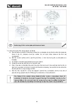
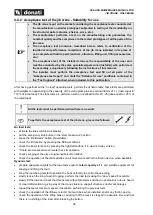
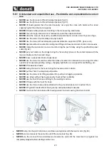
Electrical connections of the lifting unit (trolley/hoist): 


To connect the festoon power line cable in the lifting unit electrical equipment 
connector block, see the trolley/hoist “User instructions”, attached to this publication


Never make the electrical connections with the voltage on


Never make temporary connections or jump or makeshift connections


Completely tighten all of the grommets


Use the wiring diagrams corresponding to the trolley/hoist being worked on 


Summary of Contents for GRL Series

Page 1: ...JIB CRANE 360 MANUAL AND ELECTRIC CONTINUOUS ROTATION GRL SERIES USE INSTRUCTIONS INSTALLATION USE MAINTENANCE MARCH 2022 KMAN60MG00 Translated from the original instructions in Italian ...

Page 2: ......

Page 3: ...EVENTION 13 3 1 Authorised operator qualifications 13 3 2 General safety regulations 14 3 3 Safety signs 14 3 4 Warnings on residual risks 15 3 5 Safety devices and instructions 16 3 5 1 Control devices 16 3 5 2 Safety and emergency devices for GRL 16 3 5 3 Warning and notice devices Signage summary 16 4 HANDLING INSTALLATION COMMISSIONING 18 4 1 General notes for delivery 18 4 2 Packaging transpo...

Page 4: ...g the jib crane 41 5 4 Deactivating at the end of work 42 5 5 Use criteria and precautionary measures 43 5 6 Use contraindications 44 5 6 1 Unintended and unpermitted use Predictable and unpredictable incorrect use 45 6 JIB CRANE MAINTENANCE 47 6 1 Safety precautionary measures 47 6 2 Qualification of personnel assigned to maintenance 49 6 3 Maintenance plan 53 6 3 1 Daily and routine maintenance ...

Page 5: ... of this manual The manufacturer reserves the right to the material and intellectual property of this publication and forbids its dissemination and duplication including partial without prior written consent 1 2 Symbols meaning and use Certain symbols are used in this manual to call the reader s attention and underline some particularly important aspects The following table shows the list and mean...

Page 6: ...ns diagrams test logbook etc 1 4 Regulatory compliance The GRL series jib cranes are designed and constructed in consideration of the Essential Health and Safety Requirements of Annex 1 of Machinery Directive 2006 42 EC and are put on the market with the CE marking and CE Declaration of Conformity as per Annex II A of the same Directive fig 1 Example of CE Certificate fig 2 Example of UKCA Certifi...

Page 7: ...s manual and in particular always operate within the limits of use of the jib crane always perform a constant and diligent maintenance assign use of the machine to operators with a proven capacity adequately instructed for the purpose only use the original spare parts indicated by the manufacturer The intended use and the configurations of the jib are the only ones allowed Do not try to use it ign...

Page 8: ...ces which must ensure the stability and safety of the crane in all operating conditions withstanding the stress and dynamic effects induced by the overturning moment and the lifting type and speed 2 1 3 The composition of the jib cranes The composition of the jib crane is relatively simple the metalwork structure lifting unit composed of a hoist electric or manual the traverse unit formed by hoist...

Page 9: ...elf to the base foundation plinth fig 6 Counterplate with chemical bolts Upon request supplied for fixing the column itself to the floor fig 7 Finishing Protection of the metalwork structure from inclement weather and environmental agents dust gases etc is guaranteed by treatments performed using the application of yellow std RAL1007 enamel after preparing the surfaces with metallic sandblasting L...

Page 10: ...s and allows the creation of completely reliable and technically innovative machines through economies of scale Arm electric rotation device Formed by a gear motor fig 8 fixed vertically in the upper part of the arm made with a motor of epicycloid type with gears in a thermally treated oil bath and self braking conical brake motor The pinion protruding from the gear motor is coupled with a toothed...

Page 11: ...00V Collector Protection IP00 IP55 upon request Maximum voltage insulation 500V Limit switch Protection IP65 Maximum voltage insulation 300V Cables CEI 20 22 II Maximum power insulation 450 750V 2 2 3 Electrical supply The jib cranes have been designed to be powered with alternating electric current with maximum three phase voltage of 480V Standard GRL gear motor with three phase inverter 2 2 4 Am...

Page 12: ...ate or not determines by its positioning the choice of the most suitable handling lifting and travel speeds In some cases it is indispensable to use hoists with two speeds with a slow positioning speed Area of use the jib crane is characterised by its conception by intrinsic high elasticity which becomes even more evident when it is used for handling with loads close to the maximum lifting capacit...

Page 13: ...USE AND MAINTENANCE MANUAL FOR JIB CRANE GRL SERIES 9 2 2 7 Electrically rotated GRL characteristics and technical data ...

Page 14: ...USE AND MAINTENANCE MANUAL FOR JIB CRANE GRL SERIES 10 Fixing systems for jib cranes ...

Page 15: ...bolts minimum floor thickness 170mm The fixing of the pillar with chemical bolts requires a scrupulous check of suitability in relation to the type of support flooring The suitability checks are the responsibility of the user and must be carried out by expert qualified technicians who will evaluate the feasibility and formally undertake the relative responsibilities ...

Page 16: ... the pillar with chemical bolts requires a scrupulous check of suitability in relation to the type of support flooring The suitability checks are the responsibility of the user and must be carried out by expert qualified technicians who will evaluate the feasibility and formally undertake the relative responsibilities ...

Page 17: ...vent the occurrence of hazardous situations 3 1 Authorised operator qualifications To better define the field of operation and the consequent undertaking of responsibility by each OPERATOR given the specific training and achieved qualification the following table has been prepared of the professional profiles with relative pictogram necessary for all types of operation PICTOGRAM OPERATOR PROFILE A...

Page 18: ...N THE MANUAL TO HIGHLIGHT HAZARDOUS SITUATIONS PICTOGRAM MEANING Risk of being crushed during handling of suspended loads in the case of exposure of the operator or other personnel in the zones areas involved in the trajectory of the load Attention risk of being crushed by moving mechanical parts Attention risk of being drawn in and dragged by moving parts chain wheels etc Risk of electrocution be...

Page 19: ...y by complying with the instructions contained in this manual The rope and hook must be checked periodically Risk of being drawn in and or crushed following contact with the arm in rotation and or with the moving parts of the trolley hoist Attention Exposure to moving parts may create hazardous situations It is forbidden to touch the crane arm and the trolley hoist when moving or expose yourself t...

Page 20: ... crane arm both clockwise and anticlockwise is activated manually with P T pushing the load fig 10 or electrically from the pushbutton panel 3 5 2 Safety and emergency devices for GRL The GRL jib cranes are equipped with the following safety and emergency devices fig 11 1 Trolley end limit switch mechanical stops that limit the maximum stroke of the trolley along the arm beam 2 Mechanical drives i...

Page 21: ...them If a plate deteriorates and or is no longer legible including just one of the informational items shown it advisable to request another one from the manufacturer quoting the data contained in this manual or on the original plate and then replace it The plates must never be removed and it is absolutely prohibited to affix other plates on the crane without prior authorisation from DONATI SOLLEV...

Page 22: ...industrial plants with an electromechanical background equipped with work equipment and personal protection equipment in compliance with current laws on occupational safety and after having carefully read this publication After receiving the supply check and make sure that 1 The shipping data address of the recipient no of parcels etc match what is contained in the accompanying documentation trans...

Page 23: ...al system components can be delivered inside or in cardboard boxes that based on the weight to move can be with or without a pallet The standard packaging is not waterproof against rain and is designed for destinations via land and not via sea for covered and non damp environments Therefore special packaging or protections are excluded from the supply unless they are contained in the contract If n...

Page 24: ...ng and handling may be performed by crane e g mobile cranes bridge cranes etc or forklifts with adequate capacity and characteristics and the use of special equipment is not required The parcels of any accessories with a weight less than 30 kg unlike those with a weight greater than 30 kg do not show any indication of their weight and can be handled by hand Sling the crane parts with suitable equi...

Page 25: ...in the assembly of industrial plants Lifting and overhead placement of crane parts must be performed by installers equipped with o adequate and suitable personal protection equipment e g helmet gloves safety belt etc o equipment e g forklift scaffolding etc adequate for the purpose And after a careful evaluation of the following parameters o environmental characteristics of the work site e g walk ...

Page 26: ...pecially if operating in areas where other cranes or operating machines are present fig 18 4 Verify the suitability and correct operation of the mains fig 19 a correspondence of the line voltage with the voltage required for the motors b presence and suitability of the electrical line switch circuit breaker c adequacy of the cable cross section of the electrical line d presence and suitability of ...

Page 27: ...ponsibility of the user and must be carried out by expert qualified technicians who will evaluate the feasibility and assume the relative responsibilities Positioning of the foundation frame in the plinth 1 Screw the lower nuts 2 on the stay bolts 1 letting the threaded portion protrude until obtaining the corresponding protrusion ST see paragraph 2 2 7 fig 21 Carry out this operation on all 8 eig...

Page 28: ...r the bolts used e Once it has been embedded the work time when the bars need to be positioned and the time in which it is necessary not to work in order to let it harden completely are specified on the instruction booklet present in every package of bolts f After the time required for curing has elapsed position the counterplate with the hole slits if present facing upwards and fix it following t...

Page 29: ...g to the following layout if the cable 1 comes from outside push it into the pillar using a suitable fairlead 3 placed at the bottom of the pillar until it reaches hole 2 at the top fig 27 2 Set up the pillar without the arm lifting it by the upper part with appropriate equipment having put it in the sling as shown assemble it on the counterplate positioning the base plate 4 correctly and secure i...

Page 30: ... the bolts are tightened control and if needed fix the paint around the bolts in order to avoid possible corrosion After the first lifting operations it is advisable to check nut tightening again to take up any play due to settlement of the plinth Donati Sollevamenti SRL shall not be held liable for any fixings other than those indicated in fig 28 e fig 29 fig 26 fig 27 fig 28 fig 29 fig 30 fig 31...

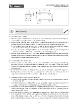
Page 31: ...y to maintain equilibrium use a rope or cord tied to the end of the arm fig 37 7 Place the arm with perforated plate on the thrust bearing matching up the holes fig 38 8 Insert the longest screws with connected flat washer from the top in the side drilled holes not threaded and tighten with nut and PAL nut 9 Insert the shortest screws with connected elastic Groover penso che questo dovrebbe essere...

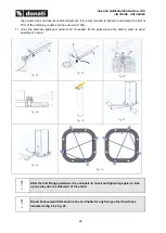
Page 32: ...collector ring under the turning plate of the arm on the specific threaded holes fig 42 Generally the collector ring must be inserted inside the column making it pass from the inspection window 12 located at the end of the column fig 43 The shortest cable will be used to connect the collector ring to the rotation equipment fig 44 making it pass through the hole drilled on the turning plate attache...

Page 33: ...eate the electrical connections on the jib crane arm proceed as follows Make all of the electrical connections between the equipment for hoist trolley control the power cable and the equipment for rotation control integrated with the gear motor as indicated in the topographical and functional wiring diagrams Wiring diagrams The wiring diagrams are supplied inside the electrical equipment and inclu...

Page 34: ...the cover into the slip ring stop fig 50 fig 47 fig 48 fig 49 fig 50 Column circuit breaker connection fig 51 1 Position the circuit breaker in the specific hole of the column connecting the relative cables to the respective terminals 2 Complete the assembly with application of the casing and the red handle Connection and adjustment of the field limit switch fig 53 1 Connect the arm rotation limit...

Page 35: ...ct cam Exit from the anomalous position with an opposite control with that of the intervention Reset the original position of contacts The customer or installer appointed by the customer must Install a line switch in the immediate vicinity of the crane to protect against short circuits indicating its function with a specific plate Make the connection of the crane structure to the earthing system a...

Page 36: ...n the lifting unit electrical equipment connector block see the trolley hoist User instructions attached to this publication Never make the electrical connections with the voltage on Never make temporary connections or jump or makeshift connections Completely tighten all of the grommets Use the wiring diagrams corresponding to the trolley hoist being worked on ...

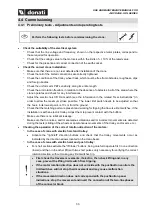
Page 37: ...eck that the matching parts are present and working for tripping the traverse limit switches if the installation is with an electric trolley Adjust them to prevent contact with the buffers Make sure there is no lubricant leakage Make sure that no noises and or anomalous vibrations and or incorrect movements are detected during the tests sliding of the wheels or spontaneous movements of the trolley...

Page 38: ...The static tests are performed with an overload factor of 1 25 load equal to 125 of the rated load All the tests must be performed when there is no wind To perform the acceptance test of the jib crane proceed as follows No load tests activate the line switch circuit breaker put the emergency stop button in the start consensus position press the start alarm button if available check the lift functi...

Page 39: ... slowly tension the sling to avoid tugging perform the load tests using the slow speed if available lift the load and stop it in suspended position at a height of 10 cm gradually apply weights on it for an overload equal to 25 of the rated capacity leave the weight suspended for a time not less than 10 minutes check that the suspended weight load overload does not give way the lifting brake and fr...

Page 40: ...ng operations Structure eliminate traces of lubrication from the structure and the trolley beam go over the hole threading and eliminate any grease residue cleaning the matching surfaces used for assembly repair any structural damage scratched surfaces crumbling paint etc Mechanisms check for any leaks and top up lubricant levels if necessary check the correct fixing of the mechanisms to the struc...

Page 41: ...g movement from a pushbutton panel with right and left buttons to control the traverse movement If the crane is equipped with a manual hoist and trolley movements are activated by mechanical activation of the hoist manoeuvre chain for the lifting movement by pushing to control the traverse trolley The arm rotation movement is activated manually by push P T or electrically from the pushbutton panel...

Page 42: ... to their chemical and physical characteristics have been classified as hazardous for example flammable explosive radioactive etc materials toxic or handful materials or products if not handled in specific safe containers for example corrosive chemical products with biological risks etc bulk food products or substances that can come into direct contact with the hoist parts or with its lubricants t...

Page 43: ...hich can generate electrostatic load accumulations In direct contact with bulk food substances 5 2 2 Danger zones and exposed persons The danger zones are all of those where in any operating phase the exposed persons can be subject to the risk that an event may occur hazardous for their safety health of psychological physical well being Specifically it is necessary to inform potentially exposed pe...

Page 44: ...and is visible from the manoeuvring position The capacity of the crane or its accessories must never be exceed by applying overloads The crane must never be equipped with lifting equipment hoist with a rated capacity over the same The lifting speed of 24 m min must never be exceeded unless the crane capacity is adequately reduced 5 2 6 Manoeuvres lifting trolley traverse and arm rotation It is a g...

Page 45: ...otor rotation directions both at slow and fast speed The lack of voltage causes an immediate block of all hoist and trolley movements since the electric motors are equipped with automatic braking devices A safety catch is installed on the lifting hook to prevent accidental unhooking of the slings and or load The lifting traverse and rotation limit switches limit the maximum vertical and horizontal...

Page 46: ... and taking care that it does not generate risks of collision or interferences with surrounding structures and or machines 2 Release the lifting hook from the slings used to handle the load 3 Lift the hook where possible to a height not under 250 cm i e so that it does not create disturbances and danger for the movement of people and things below the crane If used with a manual hoist 4 Make sure t...

Page 47: ...ot worn damaged or missing its spring catch ALWAYS check the suitability and efficiency of the slings ropes chains bands etc ALWAYS check that the track for movement of the trolley is installed at a height which does not allow the operator to interfere with the shape of the trolley hoist and or its moving parts If this is not possible install appropriate guards or signs located in the risk area fi...

Page 48: ...each test any observations related in particular to the hook chains brakes and limit switch fig 57 fig 58 fig 59 fig 60 5 6 Use contraindications The use of the jib crane for unpermitted manoeuvres its improper use and lack of maintenance may result in serious risks for the health and safety of the operator and exposed persons as well as compromise the operation and safety of the machine The actio...

Page 49: ...tact areas with the load and between the hook and slings NEVER leave a suspended load unsupervised NEVER use the crane for services other than those for which it is intended avoid using it for other operations for example painting ceilings changing light bulbs as a support for scaffolding etc NEVER lift unbalanced loads NEVER swing the load or the hook during the traverse and or rotation NEVER put...

Page 50: ...l control buttons NEVER change the functional and performance characteristics of the crane and or its components NEVER tamper with the settings of the safety devices limit switches clutch device fig 66 NEVER perform temporary repairs or reset interventions not in compliance with the instructions NEVER use non original spare parts or those not prescribed by the manufacturer NEVER entrust extraordin...

Page 51: ...ormed may cause an operator accident Pay attention to the following WARNING NOTES during the maintenance phases Before restarting the jib crane after a fault it must be carefully inspected and controlled to discover any damage and the procedure described in paragraph 5 3 must be repeated Never intervene on the setting and positioning of safety devices unless expressly required to eliminate a fault...

Page 52: ... not been left on the crane Always use protective gloves during maintenance operations All the accessible moving parts with the sole exception of the chain and subblock block are protected against accidental contacts as much as possible Replace the required guards before starting the crane again Never use sprayed water for fires disconnect all the power and use adequate fire extinguishers Make sur...

Page 53: ...nd hook and performance of simply performed maintenance activities which do not require overhead interventions e g hook thrust bearing lubrication Required technical knowledge knowledge of the functions and use of the jib crane knowledge of the lubricant used in the crane and hoist and the hazards connected with their use Required qualification suitable for work in relation to the specific operati...

Page 54: ...electrical components and safety devices used in the hoist limit switch brakes etc knowledge of average difficult electrical control and adjustment techniques replacement based on the original diagram of motors limit switch pushbutton panel control panels cables etc elementary knowledge of moderately difficult mechanical control and adjustment techniques testing of wear adjustment of mechanical st...

Page 55: ...nce in lifting and handling systems Electrical technician Typical maintenance activities electrical adjustments of safety devices calibrations and acceptance tests annual load tests routine maintenance operations including replacement of complex electrical components and or those which are critical for safety purposes lifting limit switch motors LV panel repair of electrical units after extraordin...

Page 56: ... a minimum 2 A promptly executed repair avoids additional deterioration of the crane or its components 3 Use original spare parts and products 4 The following instructions need to be complied with for maintenance work Personnel assigned to perform routine and extraordinary maintenance work must have read and clearly understood all of the indications contained in this chapter and chapter 3 Extraord...

Page 57: ...rations handled by the operator assigned to crane use general visual inspections functional tests with testing of motors limit switches clutch device brakes with no load stop button and other functions of the pushbutton panel testing of the chain and hook conditions testing of correct crane arm rotation Monthly operations handled by qualified personnel visual inspection of each mechanism and for l...

Page 58: ...Visual inspection Check wear and efficiency Hoist manual Lifting hook Visual inspection and check spring catch Check wear and efficiency Hoist manual Loading nut Chain guide Block return Check wear and efficiency Hoist manual Lifting gear motor Traverse gear motor Rotation gear motor Noise test Hoist manual Lifting motor Traverse motor Rotation motor Check correct operation Load test Hoist manual ...

Page 59: ...ability and repair any damage if necessary The brackets composed of plates and pin that form the hinged parts are subject to wear since they are mobile and swinging parts subject to radiating friction in the contact area Replace them if any excessive wear is found when they are checked All of the grub screws high resistance pins and pins must be disassembled and carefully checked along with their ...

Page 60: ...electrical system Check the efficiency of the power cable make sure there are no worn patches cuts abrasions or other alterations of the protection sheathing Check the tightening of the conductors power cable and their terminals in the connector block and if necessary tighten them correctly Check the efficiency of the conductors and earth connections checking them and fixing all of the earthing sc...

Page 61: ...aterials Clean by removing any foreign and dirty substances with vacuums absorbent cloths etc Dry any excess grease and or oil on the parts Accurate management of the jib crane mechanism lubrication is a necessary condition for guaranteeing the effective compliance to its intended service as well as its duration The lubricating power decreases over time due to stress so it is necessary to restore ...

Page 62: ...tervention of specialised or specifically trained personnel or the manufacturer s technical personnel is necessary 6 4 3 Decommissioning If it is not possible to repair the jib crane decommission it indicating the fault with a specific sign ask for intervention from the assistance service 6 5 Disassembly disposal and scrapping If the jib crane and its components because broken worn or at the end o...

Page 63: ...ncelling the warranty may compromise the correct operation of the jig crane and or its components 8 CONTROL BOOKLET To demonstrate the correct performance of all of the test and maintenance activities of the jib crane as well as to keep a record of all responsibilities in terms of the performed activities as described in this publication it is advisable to diligently fill in and maintain for the e...

Page 64: ......
Page 65: ...riportate sono di proprietà della Donati Sollevamenti S r l pertanto ne è vietata la riproduzione divulgazione ed utilizzo senza esplicito permesso Donati Sollevamenti S r l declina ogni responsabilità per errori di stampa o inesattezze e si riserva di cambiare aggiornare o modificare le informazioni presenti in qualunque momento e senza alcun preavviso KMAN60MG00 ...

Reviews: