background image

RMD10

10

X32

X12

X13

X0

7

X15

X1

X2

X22

X20

X

17

X16

X15

X09

X30

X3

X6

2A Fuse

X4

X2

X32

 wh 

(

+

)

bn 

(–)

vt (bu)

S+

Optional

L

L

N

N

Int

erface

RS232

gy (

gn)

86

bn(–)

bn

bn

rd

 (+)

rd

 (+)

12V DC Int

e

rnal

rd

 (+)

rd

 (+)

bk (-)

bk (-)

bk

bk

NTC2

y

e

 (wh) (+)

wh

rd

 (+)

rd

 (+)

NTC1

20A

rd

30

87

85

D+ (wh)

rd

  (+)

 pk (bu) (+) 

 bk (–)

bn  (–)

bn (–)

wh (y

e

) (+)

B A D

C F

E

B

A

D

C

F

1

2

5

4

7

6

8

3

9

10

11

13

14

15

16

17

21

12

18

19

20

22

23

24

25

N     PE      L

NEMA 5

i

RMD10_INM_US.book  Seite 10  Dienstag, 10. Dezember 2019  2:09 14

Summary of Contents for RMD10

Page 1: ...r FOR YOUR SAFETY Do not store or use gasoline or other flammable vapors and liquids in the vicinity of this or any other appliance WARNING Improper installation adjustment alteration service or maint...

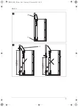
Page 2: ...NOTICE NOTICE d 90 523 mm 20 59 in 1245 mm 49 06 in 550 mm 21 65 in 523 mm 20 59 in 1245 mm 49 06 in 605 mm 23 82 in RMD 10 5 S T RMD 10 5X T S 1 RMD10_INM_US book Seite 2 Dienstag 10 Dezember 2019 2...

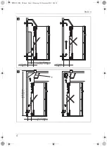
Page 3: ...RMD10 3 2 1 2 1250 mm 49 21 in 1250 mm 49 21 in 1 3 RMD10_INM_US book Seite 3 Dienstag 10 Dezember 2019 2 09 14...

Page 4: ...RMD10 4 15 25 mm 0 59 in 0 98 in 25 mm 0 98 in 25 mm 0 98 in 4 1800 mm 70 87 in 15 25 mm 0 59 in 0 98 in 1 5 RMD10_INM_US book Seite 4 Dienstag 10 Dezember 2019 2 09 14...

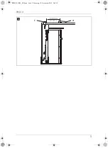
Page 5: ...RMD10 5 300 mm 11 81 in 1 2 6 RMD10_INM_US book Seite 5 Dienstag 10 Dezember 2019 2 09 14...

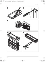
Page 6: ...RMD10 6 A 3 1 2 B 5 mm 1 97 in 5 10 mm C 1 4 1 97 3 94 in 7 RMD10_INM_US book Seite 6 Dienstag 10 Dezember 2019 2 09 14...

Page 7: ...RMD10 7 t 40 mm 1 57 in 1 2 8 3 2 1 4 9 RMD10_INM_US book Seite 7 Dienstag 10 Dezember 2019 2 09 14...

Page 8: ...RMD10 8 0 a 1 2 3 b 1 2 c d RMD10_INM_US book Seite 8 Dienstag 10 Dezember 2019 2 09 14...

Page 9: ...RMD10 9 e f 1 2 g 2 1 3 h RMD10_INM_US book Seite 9 Dienstag 10 Dezember 2019 2 09 14...

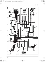
Page 10: ...N N Interface RS232 gy gn 86 bn bn bn rd rd 12V DC Internal rd rd bk bk bk bk NTC2 ye wh wh rd rd NTC1 20A rd 30 87 85 D wh rd pk bu bk bn bn wh ye B A D C F E B A D C F 1 2 5 4 7 6 8 3 9 10 11 13 14...

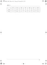
Page 11: ...RMD10 11 bk bn bu rd pk vt wh EN Black Brown Blue Red Pink Violet White FR Noir Marron Bleu Rouge Rosa Violeta Blanc RMD10_INM_US book Seite 11 Dienstag 10 Dezember 2019 2 09 14...

Page 12: ...cting the refrigerator 22 6 Technical data 27 1 Explanation of symbols A I NOTE You can find details on the operation in the manual WARNING Safety instruction Indicates a hazardous situation that if n...

Page 13: ...ly with the national regulations in Europe EN 12864 Fire hazard Ensure clean and residue free handling if silicon sealant or similar is used There is a risk of fire if silicone filaments come into con...

Page 14: ...tch off the device if applicable Avoid naked flames and sparks Air the room well Do not install the device near naked flames or other heat sources heat ers direct sunlight gas ovens etc Danger of over...

Page 15: ...he USA the installation must conform with National Fuel Gas Code ANSI Z223 1 current edition Manufactured Home Construction and Safety Standard Title 24 CFR Part 3280 Recreational Vehicles ANSI A119 2...

Page 16: ...the base of the installation niche Outlet vent fit as far above the refrigerator as possible The distance between the air inlet and outlet vents must be at least 1250 mm 49 21 in fig 3 page 3 Fit a he...

Page 17: ...door or by installing accessories such as bicycle racks while operating Install the refrigerator so that it is protected from excessive heat as this leads to poor performance and increases the power...

Page 18: ...iture B Glue the sealing lips see chapter Accessories on page 15 on the side of the furniture 4 Push the refrigerator combination against the flexible sealing lips on furniture The space behind the re...

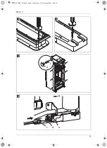
Page 19: ...deflector to prevent sludge or dirt from get ting inside while driving fig 8 2 page 7 If you have to use a roof vent instead of the air outlet vent Cut out a section in the roof Refer to the roof ven...

Page 20: ...utside under the vehicle Variant 2 Attach the condensation hose directly to the fitting intended for it on the ventilation grill fig 9 4 page 7 4 6 Install the roof vent Seal the installation frame to...

Page 21: ...on Fasten the six screws fig g 1 page 9 through the six plastic washers in the sides of the refrigerator and further into the wall Put the caps fig g 2 page 9 onto the screw heads NOTICE Only screw th...

Page 22: ...s not permitted Use a metal sealed screw connection The gas filter white in the refrigerator gas connection must not be removed Only use cylinders of propane or butane gas not natural gas or city gas...

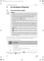
Page 23: ...hecks have been carried out refer to the authorized service provider in your area Conditions for the gas supply Ensure the following The gas supply system must incorporate a pressure regulator to main...

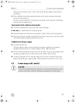
Page 24: ...ectrical components e g extra third party fans to the inter nal wiring of the refrigerator will void any claims from the guarantee and product liability The refrigerator has a CI bus interface and can...

Page 25: ...pply max 1 A options module oven fan WARNING Fire hazard The supply line to the heating element must be protected with a 20 A fuse The supply line to the electronics must be protected with a 2 A fuse...

Page 26: ...signal D from the light system to detect the running engine In automatic mode the refrigerator selects the most favorable mode available The refrigerator is only operated with direct current when the...

Page 27: ...47 l 177 l 142 l 35 l 171 l 177 l 142 l 35 l 171 l 153 l 124 l 29 l 147 l Power consumption 250 W 230 Vw 170 W 12 Vg Energy consumption 4 4 kWh 24 h 230 Vw Gas consumption 580 g 24 h Climate class SN...

Page 28: ...on des symboles A I REMARQUE Les consignes d utilisation se trouvent dans le manuel d utilisation AVERTISSEMENT Consigne de s curit signalant une situation dangereuse qui peut entra ner la mort ou de...

Page 29: ...sez uni quement des r gulateurs de pression r glage fixe correspondant aux prescriptions nationales en Europe EN 12864 Risque d incendie Assurez un traitement propre et sans traces lorsque du mastic a...

Page 30: ...pas endommager le circuit frigorifique Le r frig rant du circuit frigorifique s enflamme facilement En cas d endommagement du circuit frigorifique odeur d ammoniaque Le cas ch ant teignez le r frig r...

Page 31: ...ications sont tou tefois conditionnelles une installation effectu e conform ment aux instructions sui vantes telles qu applicables Aux tats Unis l installation doit tre conforme aux normes suivantes N...

Page 32: ...fin La paroi ext rieure doit comporter une ouverture de ventilation fig 2 1 page 3 et une ouverture d a ration fig 2 2 page 3 quip e d une grille d a ration afin que la chaleur form e puisse tre vacu...

Page 33: ...teurdetoit fig 6 1 page 5 et la sortie d air du climatiseur de toit fig 6 2 page 5 doit tre d au moins 300 mm 70 87 in Le r frig rateur ne doit pas tre install lat ralement par rapport aux ouvertures...

Page 34: ...ur 3 Poussez le r frig rateur four contre la barre de but e avecles l vres d tanch it flexibles L espace se trouvant derri re le r frig rateur est herm tiquement solidaire de l habitacle Distance d ca...

Page 35: ...rri re le r frig rateur dans la zone du br leur Prot gez l extr mit de l ouverture avec un d flecteur pour que ni boue ni salis sures ne puissent y p n trer pendant le trajet fig 8 2 page 7 Si vous av...

Page 36: ...sse l ext rieur sous le v hicule Variante 2 Fixez le tuyau de condensation directement sur le raccord pr vu sur la grille de ventilation fig 9 4 page 7 REMARQUE Utilisez uniquement des grilles de vent...

Page 37: ...s six vis fig g 1 page 9 dans les six douilles en plastique des parois lat rales du r frig rateur puis dans la niche murale Placez les bouchons fig g 2 page 9 sur les t tes des vis Pos dans fig c page...

Page 38: ...lles de gaz propane ou butane pas de gaz naturel ou gaz de ville dont la vanne de r duction de pres sion a t contr l e et un embout correspondant V rifiez que les donn es inscrites sur le r gulateur d...

Page 39: ...z le br leur pour v rifier le bon fonctionnement de la vanne de gaz du br leur et de l allumage Si l appareil ne fonctionne pas correctement une fois que toutes les v rifications ont t effectu es adre...

Page 40: ...chaudes de l unit du br leur ou avec des ar tes vives Des modifications de l installation lectrique interne ou le raccorde ment d autres composants lectriques p ex ventilateur suppl mentaire d un aut...

Page 41: ...tion CC 20 Raccordement bus CI 21 Raccordement au courant continu 22 Carter terminal 12 V vue avant AMP TE Tyco 180906 CS Colombo 63N025 23 lectronique c ble alimentation CC 24 l ment chauffant c ble...

Page 42: ...ourant continu que lorsque le moteur du v hicule est en marche Raccordez E au bus CI Raccordez 3 au signal S en option Prot gez la ligne d alimentation A avec un fusible 2 A dans le r partiteur du v h...

Page 43: ...Capacit Capacit brute Compartiment r frig rateur Compartiment conservateur Capacit nette totale 153 l 124 l 29 l 147 l 177 l 142 l 35 l 171 l 177 l 142 l 35 l 171 l 153 l 124 l 29 l 147 l Puissance a...

Page 44: ...s YOUR LOCAL DEALER dometic com dealer YOUR LOCAL SUPPORT dometic com contact dometic com 1 01 1 0 4 0 1 1 2 2 1 2 9 0 DOMETIC GROUP AB 3E 0 1 4 4445102585 289 0756 95 02 2020 RMD10_INM_US book Seite...

Reviews: