background image

13

EN

CapTouch Cabin Control Operation

Icon

Description/Mode

Function

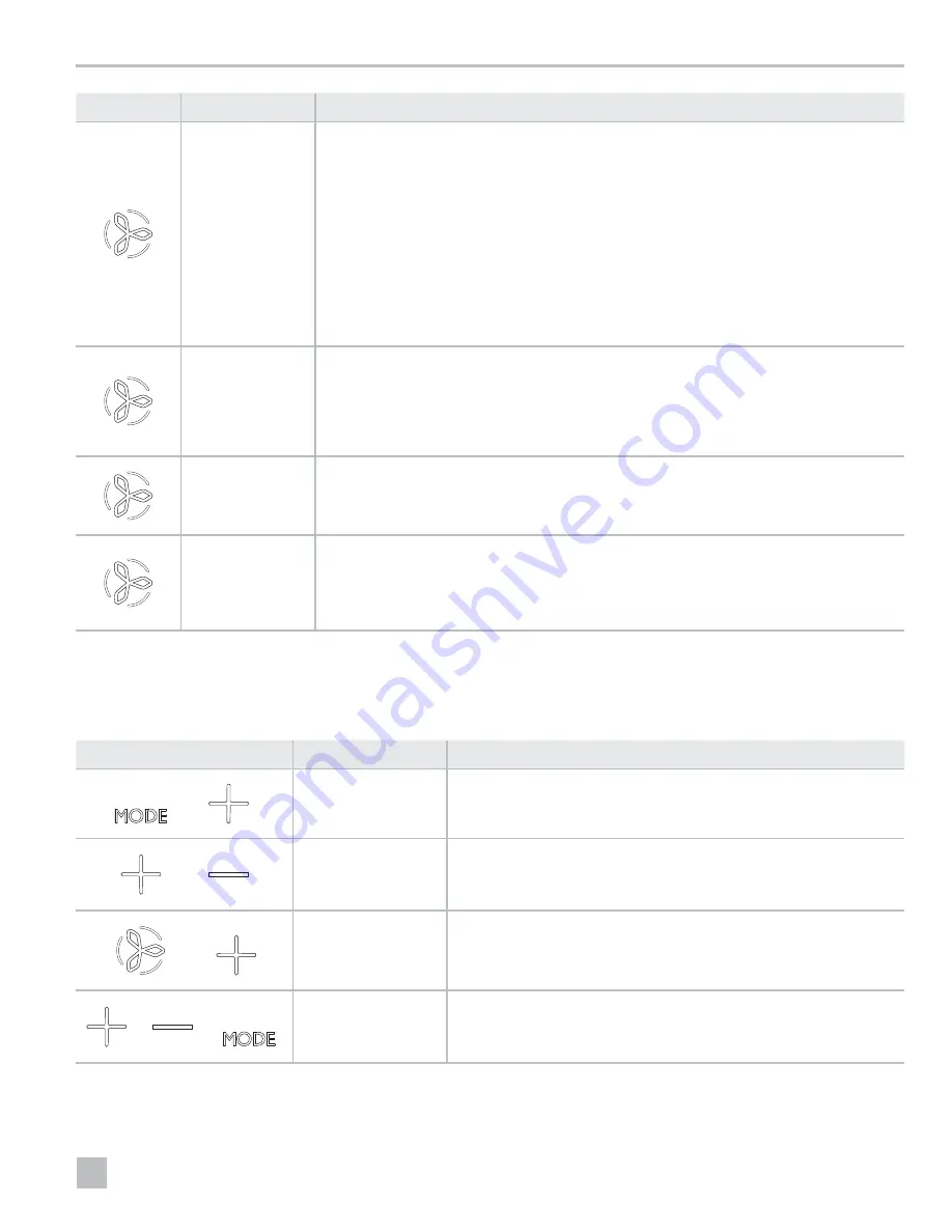
Fan

The 

Fan

 icon allows the user to cycle through all of the different fan speeds, which include auto and 

1–5 (1=low, 2=medium low, 3=medium, 4=medium high, and 5=high). Fan speeds are automatic 

based on default and programmed values. Program menu settings P-1 and P-2 determine the maximum 

and minimum fan speed settings. 
•  Fan speed decreases as the temperature set-point is approached in COOL mode and operates at 

low speed when the set point is reached. 

•  The automatic fan speed operation can be reversed for HEAT mode when parameter P-12 is set to 

“rEF”. See “Programming the Control” on page 14 for more detail.

•  Automatic fan mode determines the required fan speed based on temperature differential. 

This balances the most efficient temperature control with a slower, quieter fan speed. To select 

automatic fan mode, tap and release the 

Fan

 icon until an “A” appears on the display.


I

Refer to “Selecting a Parameter” on page 15. Once high and low fan speed limits are set, the 

unit automatically readjusts the remaining fan speeds in both automatic and manual fan modes.

Manual Fan

Manual fan allows the selection of a consistent desired fan speed. There are five manual fan speeds 

available: high, medium high, medium, medium low, and low. The speed number is illuminated on the 

display when selected. 
•  Tap and release the 

Fan

 icon to advance from automatic to manual fan operation. 

•  Tap and release the 

Fan

 icon to cycle through the manual fan speeds, from low to high. 

•  Tap and release the 

Fan

 icon to return to automatic fan operation. 

Fan-Only

Use fan-only to operate the fan for air circulation when no cooling or heating is desired. 
•  From the OFF mode, tap and release the 

Fan

 icon to select a desired fan speed. 


I

Turning the control ON reverts the fan to the AUTOMATIC mode or the last selected manual fan 

setting.

Cycled / Continuous 

Fan

The fan can be set to run continuously whenever the system is turned ON, or it can be set to cycle ON 

and OFF in conjunction with the cooling or heating cycles. 
•  Tap and hold the 

Fan

 icon for five seconds.


– CYC displays when the operational setting is set to cycled.


– CON displays when the operational setting is set to continuous.

7 .3  Using the Control Display Panel

The following table details the icon combinations to use 
to activate different functions on the control.

Icon Combination

Icon Names

Function

 & 

Mode

 & 

Up

Enter the programming menu:

Tap simultaneously and hold for three seconds while the control is in the OFF 

mode. P1 appears on the display.

 & 

Up

 & 

Down

Display the outdoor temperature:

Tap simultaneously and hold for three seconds. The display alternates between 

OU and the outdoor temperature reading while this combination is held.

 & 

Fan

 & 

Up

Display the seawater temperature:

Tap simultaneously and hold for three seconds. The display alternates between 

SE and the seawater temperature reading while this combination is held.

 & 

 & 

Up

Down

, & 

Mode

Display the relative humidity:

Tap simultaneously and hold for three seconds. The display alternates between 

HS and the relative humidity reading while this combination is held.

Summary of Contents for CapTouch

Page 1: ...L UNITS L 5119 Form No 340498 20200326 2020 Dometic Corporation WARNING Cancer and Reproductive Harm www P65Warnings ca gov CapTouch and CapTouch Wi Fi EN CapTouch Cabin Control Installation and Opera...

Page 2: ...9 Disposal 39 10 Warranty Information 39 Contents Service Center Dealer Locations Visit www dometic com Read these instructions carefully These instructions MUST stay with this product 1 Explanation...

Page 3: ...s 34 programmable parameters automatic and manual fan speeds standard and optional sensor inputs and fits both Vimar Idea and Eikon switch bezels This manual provides all necessary information for the...

Page 4: ...speeds Dometic Brand identification No operational function Up Raises the temperature set point Down Lowers the temperature set point Icon Name Function Temperature Indicator Displays the inside set p...

Page 5: ...ation Sensor optional 1 4 4 Operational Specifications Set Point Operating Range 55 F to 99 F 13 C to 37 C Ambient Temperature Operating Range Displayed 5 F to 150 F 15 C to 66 C Sensor Accuracy 2 F 7...

Page 6: ...lection Jumper J2 Low Pressure Switch Jumper Run Capacitor Low Pressure Switch High Pressure Switch Optional DC Blower Comp L1 Pump L1 Pump L2 0 10 VDC GND Fan L1 Comp L2 Compressor Display Jacks for...

Page 7: ...k Required Water Inlet Temperature Sensor Optional Outside Air Temperature Sensor JP5 Temperature Sensor Selection Jumper Ground Fan Water Valve Electric Heat Strip Fan Run Capacitor L2 L2 L2 AC L2 L1...

Page 8: ...ptional inside air temperature sensor is required if installing the display panel in a cabinet enclosed space or any area where the accurate sensing of the room temperature would be impaired This sect...

Page 9: ...rate circuit breaker be sure to turn it ON 4 Turn the display ON 5 Tap the Fan icon 6 Verify that the fan is running and that a steady airflow is coming out of the supply air grille 7 Select a tempera...

Page 10: ...e differential setting in the control parameters Refer to Selecting a Parameter on page 15 To view the current water temperature tap and hold Fan and Up simultaneously for three seconds Refer to Using...

Page 11: ...splay built in temperature sensor Installation of an optional inside air temperature sensor located in the return air path greatly increases the effectiveness of the de icing feature and this option s...

Page 12: ...the DEHUMIDIFICATION mode heat cycle will not run when the ambient temperature is below 40 F 4 C This protects the condenser coil from freezing Systems configured with electric heat will run the DEHUM...

Page 13: ...Fan icon to cycle through the manual fan speeds from low to high Tap and release the Fan icon to return to automatic fan operation Fan Only Use fan only to operate the fan for air circulation when no...

Page 14: ...sed to program and fine tune the system for the most efficient operation within an installation and to adjust operating parameters for your particular needs After new values are entered and memorized...

Page 15: ...r set to OFF or 95 For 208 240 VAC input power set to OFF or 195 P 7 De icing Cycle x OFF OFF 1 ON with 5 F 3 C Display Sensor Differential 2 ON with 7 F 4 C Display Sensor Differential Select the par...

Page 16: ...Selecting HP operates the unit in the default heat pump mode which allows for cooling reverse cycle heating or optional auxiliary electric heat Selecting CL operates the unit in COOL or optional AUX H...

Page 17: ...the value set in parameter P 18 Ar FL flashes on the display every 10 seconds until cleared Tap the Down icon to reset the value to 0 restart the timer and clear the reminder P 20 CAN Bus Unit ID x x...

Page 18: ...ter If an auxiliary electric heater is installed change this setting to EnA to allow the auxiliary electric heater to be operated independently of the reverse cycle heating In DX applications the auxi...

Page 19: ...Humidity Ambient Relative Humidity 10 Calibrate the room temperature relative humidity combination sensor to display the correct room humidity reading I IThis setting is applicable to software revisio...

Page 20: ...rts the low voltage monitor checks the AC input voltage If voltage drops below the specified setting 95 VAC 195 VAC and remains below for three minutes the system shuts down and the low AC voltage fau...

Page 21: ...CapTouch Wi Fi Logo Once downloaded use these instructions to create a user account and to add one or more thermostats to an account 7 5 1 Opening the CapTouch Wi Fi App 12 Searching Available Applic...

Page 22: ...password it can be recovered through the Sign In screen 16 Choosing a Recovery Option 1 Select Forgot username or Forgot Password 17 Recovering a Username Example 2 Enter your email address 3 Tap EMA...

Page 23: ...D and Claim Code The device ID and claim code are important when adding a thermostat to the CapTouch App The device ID and claim code combinations are unique to each thermostat If the device ID and cl...

Page 24: ...a Wireless Router The CapTouch App displays these instructions in app Follow these instructions for each thermostat added to the account 1 Register the thermostat to make sure that the ID is valid an...

Page 25: ...pTouch App I IAn Internet is not available message may appear Dismiss the notification d Tap Next 24 Choosing a Router from Your Network Setup 7 Select a router 25 Entering a Password 8 Enter the pass...

Page 26: ...device is in the same Wi Fi network as the thermostat but there is no Internet connectivity Only local connectivity exists between the smart device and the thermostat The smart device is in the same W...

Page 27: ...ng and is time based for running a cycle 2 Tap Apply Complete the following steps to change the temperature or fan speed 1 Scroll up or down in the numbered column above the setting to be changed to r...

Page 28: ...dating the Information 4 Update the information as needed 5 Tap Save 7 5 11 Adding a Thermostat to a Group 35 Adding a Thermostat to a Group 1 Tap Control to display all available groups The Group scr...

Page 29: ...s appears 38 Viewing a List of Configured Thermostats 4 Tap Subscribe A subscription screen appears 39 Selecting the Plan Devices 5 Enter the number of CapTouch devices you wish to control The number...

Page 30: ...to your account 43 Viewing the Subscription Status and Payment History 8 Scroll down on your screen to view your active subscription status or to open your payment history 9 Tap More details Details...

Page 31: ...in screen appears 46 Entering the Subscription Login 4 Enter the email address tied to the subscription account The password screen appears 47 Entering the Password 5 Perform one of the following acti...

Page 32: ...irming a Cancellation a Enter the reason for cancellation and tap Confirm Cancellation 51 Selecting Account Information 8 Select Account Information to view the contact email address This email serves...

Page 33: ...ment Methods to view the payment information Tap Add New to include an additional credit card on the account I IAlthough multiple credit cards can be added to the account only one can be marked as the...

Page 34: ...m Temperature P 25 Auto Fan Speed Temperature Differential P 26 Supply Air High Temperature Limit P 27 Idle State Delay P 28 Auxiliary Heat Enable P 29 Relative Humidity Enable P 30 Wi Fi Connectivity...

Page 35: ...ia found in the installation section of this manual Install an optional inside air temperature sensor if necessary If an optional inside air temperature sensor is already installed in the air stream e...

Page 36: ...the auxiliary electric heater is disabled Be sure the chiller is in heat mode If the air handler system is equipped with water temperature sensors check the water temperature at the digital control I...

Page 37: ...ucted The condenser coil may be too hot to touch Water should be flowing strongly out of the overflow Be sure the seacock is open and water is flowing to the pump Clean the seawater strainer Check for...

Page 38: ...ebooted circuit board and display unit continue to act oddly replace the display cable The display does not show the correct room temperature The display is showing a code for a faulty air sensor typi...

Page 39: ...A filter reminder is presented The timer setting to clean or replace the filter has been reached Clean or replace the filter and reset the filter hours 9 Disposal M M Place the packaging material in t...

Page 40: ...om dealer YOUR LOCAL SUPPORT dometic com contact YOUR LOCAL SALES OFFICE dometic com sales offices A complete list of Dometic companies which comprise the Dometic Group can be found in the public fili...

Reviews: