background image

21

UH 5947 / 25.03.19 en / 091A

Your Advantages

•  Three in one


- safe speed monitoring in automatic and set up operation


- safe standstill monitoring


- safe integrated gate monitoring

•  For safety applications up to PL e / Cat 4 and SIL 3
•  Space and costsaving, no external safe gate monitoring required
•  Simple and time saving setup without PC
•  Comfortable, menu guided configuration via frontside display
•  Reducing interruption time in production by extensive diagnostic  
 functions
•  Easy to integrate in existing drive applications
•  Suitable for all common motor feedback systems and proximity sensors
•  Copy parameter settings in other units by pressing only a push button
•  Higer safety by 2-channel mode selector, external connection
•  With adjustable ratio between 2 sensors e.g. to detect a broken shaft
•  Possible languages: english, german, french, italian, spanish

Features
•  According to


-

Performance Level (PL) e und category 4 to EN ISO 13849-1


-

SIL-Claimed Level (SIL CL) 3 to IEC/EN 62061 


-

Safety Integrity Level (SIL 3) to IEC/EN 61508

•  According to EN 60204
•  Device setting on menu-driven display or via RJ45  
  (FCC Western-Modular 8P8C) with connection cable (copy function)
•  Change tracking
•  Adjustable operation mode
  -  Automatic mode:  Monitoring of automatic rotational speed window 


and standstill speed.

  -  Setup mode: 

Monitoring of setup rotational speed window. 


Standstill is permanently enabled.

•  Single or 2-channel safety gate monitoring
•  Integrated user friendly display for parameters and operation status


- for set point and actual value of U/min or m/min


- set point display also as frequency value


- with numerous diagnostic features

•  Adjustable start up delay (0 ... 999 s)
•  Adjustable time delay for standstill detection (13/14, 23/24) (0 ... 999 s)
•  Adjustable monitoring time for feedback circuit RF1 (0,5 ... 999 s)
•  Monitoring of an release magnet
•  Monitoring of feedback circuits
•  Activation of the output path 43/44, 53/54 with on/off pushbutton with 
  short circuit detection or automatic making function
•  Adjustable PNP- or NPN-sensors
•  Connection of different encodern possible (sin/cos, TTL, HTL)
•  2-channel function
•  Forcibly guided contacts
•  LED-indicators  and 2 semiconductor monitoring output
•  With pluggable terminal blocks for easy exchange 
  of devices


- with screw terminals


- or with cage clamp terminals

•  Width 45 mm

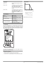
0263384

max n1

max n3

min n2

min n4

n5

AUTO

SETUP

STAND-

STILL

START (ST)

START UP

DELAY

DOOR-

ENABLE

P1

P2

EA1

EA2

STAND

(13/14)
(23/24)

STILL

38

ROTARY

(43/44)
(53/54)

68

M10368

MAG

n

t

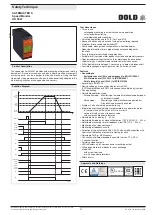
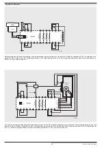
The speed monitor UH 5947 provides safe monitoring of motors and rotating 
equipment. It is used in machines and plants where machine movements 
or moving parts  can be a danger to men and machine. Using the front 
side display the parameters can be easily and comfortably adapted to the 
individual application or changed when necessary.

A025518

Canada / USA

Safety Technique

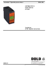
SAFEMASTER S
Speed Monitor
UH 5947

Function Diagram

Approvals and Markings

Product Description

All technical data in this list relate to the state at the moment of edition. We reserve the right
for technical improvements and changes at any time.

Summary of Contents for SAFEMASTER S UH 5947

Page 1: ...FEMASTER S Drehzahlwächter UH 5947 0263041 Datenblatt Betriebsanleitung DEUTSCH E DOLD SÖHNE KG Postfach 1251 78114 Furtwangen Deutschland Telefon 49 7723 6540 Fax 49 7723 654356 dold relays dold com www dold com Original DE EN FR ...

Page 2: ...sbeschreibung 8 Geräte und Funktionsbeschreibung 9 Konfigurationshinweise 10 Konfigurationsbeispiele 10 Konfigurationsbeispiele 11 Technische Daten 11 Technische Daten 12 UL Daten 12 EAC Daten 12 Standardtype 12 Zubehör 12 Vorgehen bei Störungen 13 Fehlerbehandlung 13 Kennlinie 13 Anwendungsbeispiele 14 Anwendungsbeispiele 15 Beschriftung und Anschlüsse 49 Maßbild Maße in mm 50 Montage Demontage d...

Page 3: ...offen werden ACHTUNG Warnt vor Handlungen die einen Schaden oder eine Fehlfunktion des Gerätes der Geräteumgebung oder der Hard Software zur Folge haben können nfo INFO Bezeichnet Informationen die Ihnen bei der optimalen Nutzung des Produktes behilflich sein sollen Die hier beschriebenen Produkte wurden entwickelt um als Teil einer Gesamtanlage oder Maschine sicherheitsgerichtete Funktionen zu üb...

Page 4: ...4 UH 5947 25 03 19 de 091A ...

Page 5: ...rüberwachung benutzerfreundliches frontseitiges Display für komfortable menügeführte Parametrierung für Soll und Istwertanzeige in U min oder m min Sollwertanzeige zusätzlich auch als Frequenzwert einstellbare Anlaufüberbrückung 0 999 s einstellbare Freigabeverzögerungszeit 0 999 s einstellbare Abschaltüberwachung für externe Schütze an RF1 0 5 999 s Überwachung eines Freigabemagneten Überwachung ...

Page 6: ... E2 T2 U1 EA1 P1 U2 T1 GND RF1 RF2 38 ST MAG GND T3 68 T4 13 23 43 53 14 24 44 54 K1 K3 K2 K4 Encoder Klemmenbezeichnung Signalbeschreibung A1 L A2 N U1 U2 Versorgung für Initiatoren bzw NAMUR Sensoren GND Versorgung für Initiatoren E1 E2 Messausgang von Initiatoren bzw NAMUR Sensoren 13 14 23 24 43 44 53 54 Schließer zwangsgeführt für Frei gabekreis 38 68 Halbleiter Meldeausgang T1 T2 T3 T4 Steue...

Page 7: ...chreibung Beim Öffnen der Positionsschalter müssen die Kontakte P1 und P2 inner halb von t 1 0 s geöffnet werden Ist die Gleichzeitigkeit nicht erfüllt er scheint eine Diagnosemeldung auf dem Display Nach dem Beheben des Fehlers ist ein Reset siehe Fehlerbehandlung oder ein Neustart durch Aus und wieder Einschalten der Versorgungsspannung erforderlich Zum Starten des Ausgangskontaktes 43 44 53 54 ...

Page 8: ...bgeschaltet Parametrierung Parametrierung und Steckerbelegung der RJ45 Schnittstelle Die RJ45 Schnittstelle dient bei entsprechender Konfiguration des UH 5947 zum Anschluss eines Encoders an das Gerät Dazu müssen alle vier Signalleitungen A A B B und GND mit dem Encoder verbun den werden Des weiteren kann die Schnittstelle mit entsprechendem Verbindungska bel OA 5947 100 siehe Zubehör zur Parametr...

Page 9: ...verzögerung 5 0 s Abschaltüberwachung 5 0 s Esc OK 1 9 Startart manueller Start x automatischer Start Esc OK 1 10 Schutztürüberwachung Gleichzeitigkeit an x Gleichzeitigkeit aus Esc OK Esc OK 2 Displayeinstellungen 2 1 Sprachen english x deutsch français español italiano Esc OK 2 2 Kontrast 50 Esc OK 2 3 Beleuchtung aus 3 s 10 s x 1 min 5 min an Esc OK 2 4 Diagnose nicht anzeigen anzeigen x Esc OK...

Page 10: ... Übersetzung 50 1 Die einzustellenden Drehzahlgrenzen U min beziehen sich auf die Dreh zahl am Initiator E1 Fall B Geberauswahl E1 E2 Initiatorauflösung E1 4 Imp U Initiatorauflösung E2 4 Imp U Übersetzung 1 1 da an gleicher Stelle gemessen wird Die einzustellenden Drehzahlgrenzen U min beziehen sich auf die Dreh zahl am Initiator E1 Fall C Geberauswahl Encoder E2 Encoderauflösung 512 Imp U Initia...

Page 11: ...1 1 UN Nennfrequenz AC 50 60 Hz Frequenzbereich AC 45 65 Hz max Restwelligkeit DC 48 Nennverbrauch AC DC 6 5 W DC 5 W Mindestausschaltdauer AC DC 600 ms DC 150 ms Messgenauigkeit 2 Schalthysterese 6 25 Initiatoren Versorgungsspannung DC 24 V wird vom Gerät bereitgestellt Stromaufnahme max 30 mA Ausgang wahlweise PNP oder NPN Spannung an E1 und E2 min DC 10 V Mindestimpuls bzw Pausendauer 75 ms Ein...

Page 12: ...Str PT Klemme AWG 24 16 Sol Str nfo Fehlende technische Daten die hier nicht explizit angegeben sind sind aus den folgenden allgemein gültigen technischen Daten zu entnehmen Nennspannung UN DC 24V nfo Fehlende technische Daten die hier nicht explizit angegeben sind sind aus den folgenden allgemein gültigen technischen Daten zu entnehmen Technische Daten UL Daten EAC Daten UH 5947 04PS 61 DC 24 V A...

Page 13: ...erhalb des Einstellbereichs Vorgehen bei Störungen Werden am bzw im Gerät Fehler erkannt so werden diese am Display mit derentsprechendenMeldungangezeigt IstaufgrunddesFehlerseinReset desGeräteserforderlich somusszunächstderFehler unddiedazugehörige Diagnosemeldung quittiert werden Anschließend muss die linke Taste ca 3 Sekunden gedrückt werden um einen Reset des Gerätes auszulösen Das Gerät enthä...

Page 14: ...ei Handstart Ein Taster an T4 ST bei Autostart Brücke an T4 ST geeignet bis SIL3 Performance Level e Kat 4 Voraussetzung für Kat 4 ist dass bei längeren Stillstandszeiten eine Zwangsdynamisierung t 24 h durchgeführt wird M10326_c P1 P2 U2 E2 GND GND E1 U1 EA1 EA2 T1 T2 43 53 44 54 MAG Encoder UH5947 Motor RF2 13 23 Stillstand 14 24 ST EO RJ45 RF1 T4 T3 L A1 68 38 Ein S1 N A2 Automatik Einricht M10...

Page 15: ...raussetzung für Kat 4 ist dass bei längeren Stillstandszeiten eine Zwangsdynamisierung t 24 h durchgeführt wird M10328_c Ein S1 ST1 ST2 Schutztüre geschlossen P1 E1 M E2 EA1 T1 23 MAG 13 ST T4 N L A1 öffnen Magnet Türfreigabe P1 P2 U2 E2 GND GND E1 U1 EA1 EA2 T1 T2 43 53 44 54 MAG UH5947 001 RF2 13 23 Stillstand 14 24 ST EO RJ45 RF1 T4 T3 A1 A2 68 38 Automatik Einricht M10329_d Ein Schutztüre gesc...

Page 16: ...16 UH 5947 25 03 19 de 091A E DOLD SÖHNE KG D 78114 Furtwangen e mail dold relays dold com internet http www dold com Postfach 1251 Telefon 0 77 23 654 0 Telefax 0 77 23 654 356 ...

Page 17: ... S Speed Monitor UH 5947 Datasheet Operating Instructions ENGLISH E DOLD SÖHNE KG P O Box 1251 D 78114 Furtwangen Germany Tel 49 7723 6540 Fax 49 7723 654356 dold relays dold com www dold com Translation of the original instructions 0263041 ...

Page 18: ...on 25 Notes for Configuration 26 Configuration Examples 26 Configuration Examples 27 Technical Data 27 Technical Data 28 UL Data 28 EAC Data 28 Standard Type 28 Variants 28 Accessories 28 Troubleshooting 29 Fault Handling 29 Maintenance and Repairs 29 Characteristics 29 Application Examples 30 Application Examples 31 Labeling and connections 49 Dimensions dimensions in mm 50 Mounting disassembly o...

Page 19: ...ATTENTION Warns against actions that can cause damage or malfunction of the device the device environment or the hardware software result nfo INFO Referred information to help you make best use of the product Symbol and Notes Statement The installation must only be done by a qualified electrican Do not dispose of household garbage The device must be disposed of in compliance with nationally applic...

Page 20: ...20 UH 5947 25 03 19 en 091A ...

Page 21: ...friendly display for parameters and operation status for set point and actual value of U min or m min set point display also as frequency value with numerous diagnostic features Adjustable start up delay 0 999 s Adjustable time delay for standstill detection 13 14 23 24 0 999 s Adjustable monitoring time for feedback circuit RF1 0 5 999 s Monitoring of an release magnet Monitoring of feedback circ...

Page 22: ...lication Functions DEVICE green Run green flashing Parameterization mode red flashing Parameterization error red Device fault K1 K2 green Output contact 13 14 23 24 closed green flashing Stop monitoring feedback loop 2 failed K3 K4 green Output contact 43 44 53 54 closed green flashing Stop monitoring feedback loop 1 failed SF OFF no failure red external failure DISPLAY Status indication Alarms di...

Page 23: ...49 1 and SIL3 as per IEC EN 61508 the position switches are connected via two channels The position switches are monitored for silmultaneity When the position switches are opened the contacts P1 and P2 must be opened within t 1 0 sec A diagnostic alarm appears on the display when the simultaneity is not met Once the fault is eliminated a reset see fault handling or a restart by switching off and b...

Page 24: ... speed does not correspond to the device s accuracy and is only designed for diagnostic purposes In the case of wiring errors and system failures corresponding diagnostic messages are displayed on the display unless they are deliberately disa bled in the parameterization Parameterization Parameterization and pin assignment of the RJ45 interface When the UH 5947 is appropriately configured the RJ45...

Page 25: ...ill 10 m min Esc OK 1 8 Times Start override 5 0 s Release delay 5 0 s Switch off monit 5 0 s Esc OK 1 9 Start type Manual start x Automatic start Esc OK 1 10 Prot door monit Simultaneity on x Simultaneity off Esc OK Esc OK 2 Display settings 2 1 Languages english x deutsch français español italiano Esc OK 2 2 Contrast 50 Esc OK 2 3 Lighting Off 3 s 10 s x 1 min 5 min On Esc OK 2 4 Diagnosis Do no...

Page 26: ...er to the rotational speed on proximity sensor E1 Case B Sensor selection E1 E2 Proximity sensor resolution E1 4 pulses rev Proximity sensor resolution E2 4 pulses rev Gear ratio 1 1 as measuring is on the same location The speed limits rpm to be set refer to the rotational speed on proximity sensor E1 Case C Sensor selection Encoder E2 Encoder resolution 512 pulses rev Proximity sensor resolution...

Page 27: ...xamples Input Nominal voltage UN AC DC 110 240 V DC 24 V Voltage tolerance AC DC 0 8 1 2 UN DC 0 9 1 1 UN Nominal frequency AC 50 60 Hz Frequency range AC 45 65 Hz max residual ripple DC 48 Nominal consumption AC DC 6 5 W DC 5 W Min Off time 150 ms Measuring accuracy 2 Hysteresis 6 25 Initiators Input current DC 24 V provided by the device Output as option PNP or NPN Voltage on E1 and E2 min DC 10...

Page 28: ...erature 60 C Pilot duty B300 2A 250Vac resistive only Ambient temperature 40 C Pilot duty B300 5A 250Vac resistive only Wire connection 60 C 75 C copper conductors only Plugin screw terminal AWG 28 12 Sol Str Torque 0 5 Nm Plugin cage clamp terminal AWG 24 12 Sol Str Plugin twin cage clamp terminal AWG 24 16 Sol Str nfo Technical data that is not stated in the UL Data can be found in the technical...

Page 29: ...ing When faults are detected on or in the device they are indicated on the display by an appropriate message If a reset of the device is necessary due to the fault at first the alarm and the associated diagnostic message have to be acknowledged Then the left key has to be pressed for approx 3 sec to initiate a reset of the device If a system failure is detected again after restart the device must ...

Page 30: ...gate monitoring active for manual start ON OFF pushbutton to T4 ST for automatic start jumper to T4 ST suited up to SIL3 Performance Level e Cat 4 Requirement for Cat 4 is that during longer periods of standstill a forced dynamisation t 24 h has to be carried out M10370_c P1 P2 U2 E2 GND GND E1 U1 EA1 EA2 T1 T2 43 53 44 54 MAG Encoder UH5947 Motor RF2 13 23 Standstill 14 24 ST EO RJ45 RF1 T4 T3 L ...

Page 31: ...erformance Level e Cat 4 Re quirement for Cat 4 is that during longer periods of standstill a forced dynamisation t 24 h has to be carried out M10377_c S1 ST1 ST2 P1 E1 M E2 EA1 T1 23 MAG 13 ST T4 N L A1 P1 P2 U2 E2 GND GND E1 U1 EA1 EA2 T1 T2 43 53 44 54 MAG UH5947 001 RF2 13 23 14 24 ST EO RJ45 RF1 T4 T3 A1 A2 68 38 On Open Guard door closed Solenoid Door enable Standstill Automatic Setup Guard ...

Page 32: ...32 UH 5947 25 03 19 en 091A E DOLD SÖHNE KG D 78114 Furtwangen e mail dold relays dold com internet http www dold com POBox1251 Telephone 49 7723 654 0 Telefax 49 77 23 654 356 ...

Page 33: ...rôleur de vitesse de rotation UH 5947 Fiche Technique Manuel d utilisation FRANÇAIS E DOLD SÖHNE KG B P 1251 78114 Furtwangen Allemagne Tél 49 7723 6540 Fax 49 7723 654356 dold relays dold com www dold com Traduction de la notice originale 0263041 ...

Page 34: ...nctions 41 Recommandations de configuration 42 Exemples de configuration 42 Exemples de configuration 43 Caractéristiques techniques 43 Caractéristiques techniques 44 Données UL 44 Données EAC 44 Versions standard 44 Accessoires 44 Diagnostics des défauts 45 Traitement des erreurs 45 Entretien et remise en état 45 Courbe caractéristiques 45 Exemples de raccordement 46 Exemples de raccordement 47 M...

Page 35: ... dommages au materiel Software ou hardware suite à un mauvais fonctionne ment de l appareil ou de l environnement de l appareil nfo INFO Concerne les informations qui vous sont mises à disposition pour le meilleur usage du produit Explication des symboles et remarques L installation ne doit être effectuée que par un electricien qualifié Ne pas jeter aux ordures ménagères L appareil doit être élimi...

Page 36: ...36 UH 5947 25 03 19 fr 091A ...

Page 37: ...se nulle 0 999 s Temporisation de détection d ouverture de boucles de retour 0 5 999 s Modes de fonctionnements règlables Mode automatique Surveillance en automatique d une fenêtre de vitesse et de la vitesse nulle Mode de réglage Surveillance d une fenêtre de vitesse de réglage et de la vitesse nulle Surveillance de porte mono canal ou bi canaux Surveillance de la gâche de porte Activation des li...

Page 38: ... U2 T1 GND RF1 RF2 38 ST MAG GND T3 68 T4 13 23 43 53 14 24 44 54 K1 K3 K2 K4 Encoder Réalisation et fonctionnement Utilisations Schéma Affichages Repérage des bornes Description A1 L A2 N U1 U2 Alimentation des sondes NPN PNP et NAMUR GND Alimentation pour sondes E1 E2 Sortie de mesure pour les sondes NPN PNP ou NAMUR 13 14 23 24 43 44 53 54 Contacts NO liés pour circuit de déclenchement 38 68 So...

Page 39: ...de protection à gâchette Les interrupteurs de position sont connec tés sur deux canaux afin d obtenir les catégories les plus élevées niveau de performance E conformément à EN ISO 13849 1 et SIL 3 conformé ment à CEI EN 61508 Le système surveille la simultanéité des interrupteurs de position Les con tacts P1 et P2 doivent être ouverts dans un espace de t 1 0 s Lorsque la simultanéité n est pas gar...

Page 40: ... à la préci sion de l appareil et est uniquement prélevée pour des fins de diagnostic En cas d erreurs de câblage et de système les messages de diagnostic correspondants s affichent sur l écran à mois que celles ci sont arrêtées de façon ciblée en mode de paramétrage Paramétrage Paramétrage et occupation des connecteurs de l interface RJ45 L interface RJ45 est destinée à la connexion d un encodeur...

Page 41: ...etard validation 5 0 s Surveillance coupure 5 0 s Esc OK 1 9 Type démarrage Démarrage manuel x Démarrage auto Esc OK 1 10 Surv p sécurité Simultanéité ON x Simultanéité OFF Esc OK Esc OK 2 Réglages affichage 2 1 Langues english x deutsch français español italiano Esc OK 2 2 Contraste 50 Esc OK 2 3 Éclairage OFF 3 s 10 s x 1 min 5 min ON Esc OK 2 4 Diagnostic ne pas afficher afficher x Esc OK 2 5 M...

Page 42: ...tesse de rotation au détecteur E1 Cas B Choix du capteur E1 E2 Résolution du détecteur E1 4 Imp U Résolution du détecteur E2 4 Imp U Rapport de transmission 1 1 da an gleicher Stelle gemessen wird Les limites de vitesse de rotation à régler t min se réfèrent à la vitesse de rotation au détecteur E1 Cas C Choix du capteur Encodeur E2 Résolution de l encodeur 512 Imp U Résolution du détecteur E2 4 I...

Page 43: ... DC 24 V Tolérance de tension AC DC 0 8 1 1 UN DC 0 9 1 1 UN Fréquence assignée AC 50 60 Hz Plage de fréquence AC 45 65 Hz Ondul résiduelle max DC 48 Consommation nominale AC DC 6 5 W DC 5 W Durée minimale de coupure AC DC 600 ms DC 150 ms Précision de mesure 2 Hystérésis de couplage 6 25 Initiateurs Tension d alimentation DC 24 V Délivré par l appareil Consommation 30 mA max Sortie en option PNP ...

Page 44: ...ive only 5A 24Vdc resistive only UN AC DC 110 240 V Température ambiante 60 C Pilot duty B300 2A 250Vac resistive only Température ambiante 40 C Pilot duty B300 5A 250Vac resistive only Connectique uniquement pour 60 75 C bornes à vis AWG 28 12 Sol Str Torque 0 5 Nm bornes ressorts AWG 24 12 Sol Str bornes ressorts deTWIN AWG 24 16 Sol Str nfo Les valeurs techniques qui ne sont pas spécifiées ci d...

Page 45: ...ce est hors spectre de réglage Diagnostics des défauts Lorsque l appareil détecte une erreur le message correspondant s affiche sur l écran Lorsqu il est nécessaire de réinitialiser l appareil en raison d une erreur l erreur et le message de diagnostic correspondant doivent être acquittés Ensuite actionner la touche gauche pendant env 3 sec afin de déclencher la réinitialisation de l appareil Si u...

Page 46: ...tivé en manuel BP à T4 ST en Auto pont à T4 ST convient jusqu à SIL3 Performance Level e Cat 4 Condition pour la Cat 4 Dynamisation forcée après des arrêts prolongés t 24 h M10371_c P1 P2 U2 E2 GND GND E1 U1 EA1 EA2 T1 T2 43 53 44 54 MAG UH5947 RF2 13 23 14 24 ST EO RJ45 RF1 T4 T3 L A1 68 38 S1 N A2 Marche Encodeur Moteur Arrêt Automatique Ajustement S1 ST1 ST2 P1 E1 M E2 EA1 T1 23 MAG 13 ST T4 N ...

Page 47: ...e Cat 4 Condition pour la Cat 4 Dynamisation forcée après des arrêts prolongés t 24 h M10378_c S1 ST1 ST2 P1 E1 M E2 EA1 T1 23 MAG 13 ST T4 N L A1 P1 P2 U2 E2 GND GND E1 U1 EA1 EA2 T1 T2 43 53 44 54 MAG UH5947 001 RF2 13 23 14 24 ST EO RJ45 RF1 T4 T3 A1 A2 68 38 Ouvrir Porte fermée Solénoid Déverrouillage porte Arrêt Automatique Ajustement Marche Porte fermée Roue dentée Axe Moteur Transmission Ra...

Page 48: ...48 UH 5947 25 03 19 fr 091A E DOLD SÖHNE KG D 78114 Furtwangen e mail dold relays dold com internet http www dold com B P 1251 Téléphone 49 77 23 654 0 Téléfax 49 77 23 654 356 ...

Page 49: ...G 24 to 12 2 x 0 2 1 0 mm2 2 x AWG 24 to 18 A 10 mm 1 x 0 2 2 5 mm2 1 x AWG 24 to 12 A 8 mm 1 x 0 2 1 5 mm2 1 x AWG 24 to 16 M10249 A A 7 mm 1 x 0 25 2 5 mm2 1 x AWG 24 to 12 2 x 0 25 1 0 mm2 2 x AWG 24 to 18 A 10 mm 1 x 0 25 2 5 mm2 1 x AWG 24 to 12 2 x 0 25 1 5 mm2 mit TWIN Aderendhülse A 8 mm 1 x 0 25 1 5 mm2 1 x AWG 24 to 16 M10250 A A 7 mm 1 x 0 2 2 5 mm2 1 x AWG 24 to 12 2 x 0 2 1 5 mm2 2 x ...

Page 50: ...EN Dimensions dimensions in mm FR Dimensions dimensions en mm DE Montage Demontage der PS PC Klemmenblöcke EN Mounting disassembly of the PS PC terminal blocks FR Montage Démontage des borniers PS PC M10336 Hutschiene DIN EN 60715 122 6 107 35 45 3 M4826_a _ ...

Page 51: ... Verbindung zwischen Encoder Steuerung und dem Drehzahlwächter Er ist für Steuerungen von Siemens Heidenhain mit folgender PIN Belegung ausgelegt EN 25 pole adaptor to connect an encoder or for controllers of Sie mens Heidenhain with corresponding PIN arrangement see re marks for accessories in operating manual FR Adaptateur de liaison à 25 poles pour le branchement du codeur ou pour le branchemen...

Page 52: ...ndaten gelten für die Standardtype Sicherheitstechnische Kenndaten für andere Geräteausführungen erhalten Sie auf Anfrage Die sicherheitstechnischen Kenndaten der kompletten Anlage müssen vom Anwender bestimmt werden EN The values stated above are valid for the standard type Safety data for other variants are available on request The safety relevant data of the complete system has to be determined...

Page 53: ...53 UH 5947 25 03 19 de en fr 091A DE EG Konformitätserklärung EN CE Declaration of Conformity FR Déclaration de conformité européenne ...

Page 54: ...54 UH 5947 25 03 19 de en fr 091A ...

Page 55: ...8 Zeiten Anlaufüberbrückung s Freigabeverzögerung s Abschaltüberwachung s 1 9 Startart manueller Start automatischer Start 1 10 Schutztürüberwachung Gleichzeitigkeit an Gleichzeitigkeit aus Bitte heraustrennen und sicher aufbewahren Parametrierung anhand des Displays Um in den Parametriermodus des Gerätes zu gelangen ist folgende Tastenkombination vorgesehen Als erstes muss die rechte Taste betäti...

Page 56: ...56 UH 5947 25 03 19 de en fr 091A E DOLD SÖHNE KG D 78114 Furtwangen e mail dold relays dold com internet http www dold com Postfach 1251 Telefon 0 77 23 654 0 Telefax 0 77 23 654 356 ...

Page 57: ...47 Device No Configurated by Date 1 Parameterization 1 1 Monitored motion 1 Translational Rotational 1 2 Encoder type 1 Lin encoder Rot encoder 1 3 Encoder selection RJ45 Encoder E2 RJ45 Encoder E1 E2 1 4 Lead transm Transmission 1 Lead mm 1 5 Encoder settings Signal form sin cos or TTL x HTL Resolution xxxxxx e g xxx xxx Imp U e g mm 1 6 Sensor settings Sensor type pnp npn Resolution E1 Imp U e g...

Page 58: ...58 UH 5947 25 03 19 de en fr 091A E DOLD SÖHNE KG D 78114 Furtwangen e mail dold relays dold com internet http www dold com POBox1251 Telephone 49 7723 654 0 Telefax 49 7723 654 356 ...

Page 59: ...0 m min Arrêt 10 m min Appareil UH 5947 No de appareil Configuration effectuée par Date 1 Paramétrage 1 1 Déplac surveillé 1 Translation Rotation 1 2 Type de capteur 1 Capteur lin Capteur rot 1 3 Sélection capteur RJ45 codeur E2 RJ45 codeur E1 E2 1 4 Pas rap transm Transmission 1 Pas mm 1 5 Réglage codeur Forme de signal sin cos ou TTL x HTL Résolution xxxxxx ou xxx xxx Imp U ou mm 1 6 Réglage ini...

Page 60: ...60 UH 5947 25 03 19 de en fr 091A E DOLD SÖHNE KG D 78114 Furtwangen e mail dold relays dold com internet http www dold com B P 1251 Téléphone 49 77 23 654 0 Téléfax 49 77 23 654 356 ...

Reviews: