INSTALLATION SHEET
Ether-Com XR
Description
The Ether-Com XR
™
Single Port Router allows a DMP XR200, XR200-485, or XR2400F Command Processor™ panel to
communicate with a DMP SCS-1 Receiver over an existing Ethernet network. Operating as an interface between the
panel and the network, the Ether-Com XR™ mounts inside the panel enclosure and is powered by the panel. The panel
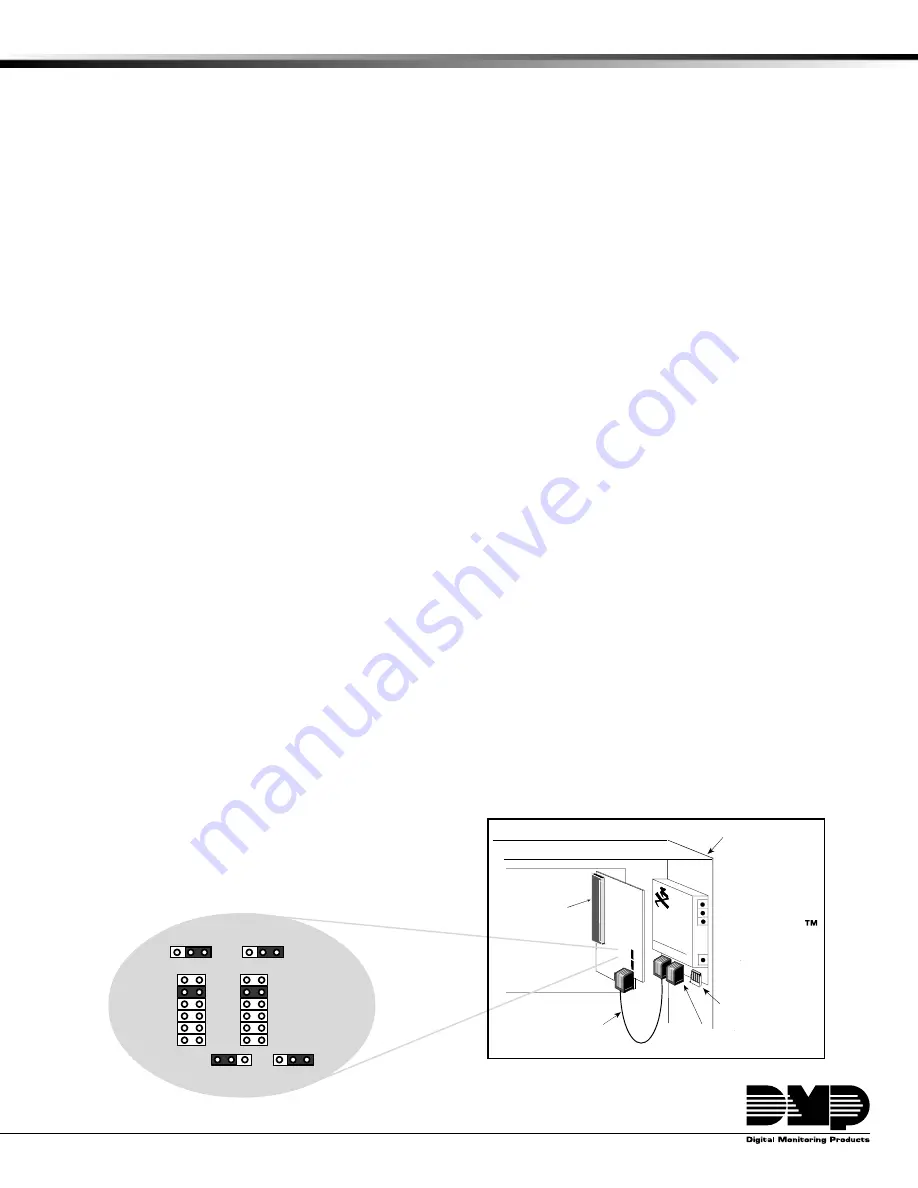
communicates to the Ether-Com XR through a 462N Network Interface Card as shown in Figure 1. This product is for
use with a UL listed alarm control from DMP. This unit may only be connected to a UL limited power supply.
What is included
The Ether-Com XR includes the following:
• Ether-Com XR™ Single Port Router
• Power cable
• Model 356-2 serial cable
What is needed
Additional equipment needed to install and program the Ether-Com XR:
• 386 or better PC
• Windows
™
with a communication software package such as Hyperterminal
™
• DMP Model 396 programming cable
• 10BaseT Ethernet cable
• DMP XR200, XR200-485, XR2400F and a 462N Network Interface Card
Hardware installation
1. Installation may only be performed by installation personnel.
2. Install the Ether-Com XR into the 3-hole pattern of the panel enclosure as shown in Figure 1.
3. Connect a 10BaseT Ethernet cable from your network to the network connector (J4) of the Ether-Com XR.
4. Connect the Model 356-2 serial cable from the Ether-Com XR’s serial connector (J3) to the 462N Network
Interface Card’s network cable connector (J7), as shown in Figure 1. Refer to LT-0209 Installation Sheet
for instructions to install and setup the 462N Network Interface Card.
Note
: To program the Ether-Com XR, you must use a 396 programming cable. Refer to
Programming
on
pages 2-4 of this guide for further instruction.
5. Plug the power cable connector into the J1 connector of the Ether-Com XR.
6. Connect the red wire of the power cable to screw terminal 7 on the processor panel. The power
requirement for the router is 200mA @ 9-14 VDC.
7. Connect the black wire of the power cable to screw terminal 10 on the processor panel.
Note
: If you are extending the power cable, crimp connectors must be used.
B
ETHER-COM
XR200 Panel
J6
Expansion
Connector
462N
Network
Connector
Power
Connector
Model 356-2
Serial Cable
J7
350 Enclosure
Ether-Com XR
Figure 1: Ether-Com XR Installation
RXD
= NO
TXD
= NO
Baud Rate
= 9600
J3
= FORCE
J6
= HST
462N jumper settings
EXT
9600
4800
2400
1200
300
FORCE
CTS
J3
J2
J5
RXD
TXD
YES
NO
J1
YES
NO
J4
DNET
J6
HST


