background image

Digital Monitoring Products, Inc  |  7000INT Series Installation and Programming Guide  

11

TAMPER PROTECTION

1. 

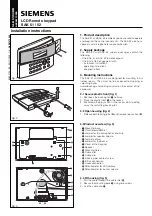
Insert the included tamper puck into the base. See Figure 6.

2.  Secure the tab to the wall with a #6 screw.
3.  Ensure all cables are routed through the housing holes before fully mounting the 

base to the wall. 

4.  Use #6 screws to secure the keypad base to the surface. 
5.  Place the keypad cover back onto the base and snap into place. 

Note: 

All DMP keypad housings are designed to install on any 4” square box, 

3-gang switch box, DMP 695 and 696 back-box, or a flat surface. 

MOUNT THE KEYPAD

Summary of Contents for 7000INT Series

Page 1: ...FRI 2 52 PM 1 2 3 4 5 6 7 8 9 0 CMD A C B D F E G I H J L K V X W S U T P R Q M O N Y Z ENTE R BACK INSTALLATION AND PROGRAMMING GUIDE 7000INT Series International ThinlineTM Keypad ...

Page 2: ......

Page 3: ... Control Reader 7 Wire the Electronic Lock 9 Wire the 333 Suppressor 9 Mount the Keypad 11 Tamper Protection 11 Program the Keypad 13 Keypad Options 13 Custom Card Format 18 Additional Programming 24 Proximity Credential Compatibility 24 Program a Credential 24 Test the Keypad 25 Arm and Disarm the System 27 Area System Type 27 All Perimeter System Type 27 End User Training 27 Home Sleep Away Syst...

Page 4: ...0 Public Card Formats 31 Readers and Credentials 32 Compliance Specifications 34 Specifications 34 Compatibility 34 What Is Included 34 Accessories 34 International Certifications 35 Security Grade 3 35 Environment Class II 35 Intertek ETL Listed 35 ...

Page 5: ...nection to a 4 wire keypad bus and optional backboxes for conduit or wall mount applications Each model provides its own distinct functionality See Figure 1 for keypad features 7063 WINT Built in proximity card reader designed to read proximity credentials 7073 WINT Provides a door strike relay and allows Wiegand input from external card readers Provides a built in proximity card reader designed t...

Page 6: ...PAD FEATURES FRI 2 52 PM 1 2 3 4 5 6 7 8 9 0 CMD A C B D F E G I H J L K V X W S U T P R Q M O N Y Z ENTE R BACK Armed Power LEDs Proximity Credential Reader and Backlit Logo Keypad Display Status List Select Keys Panic Keys Command CMD Key Back Arrow Key 1 4 3 2 Figure 1 Keypad Features ...

Page 7: ...he Select Key for the character and press that select key on the keypad Press that select key again for the lowercase letter Latin characters only 4 When the desired character displays on the keypad return to step 1 to enter another character or press CMD if finished NUMBER SELECT KEY 1 2 3 4 1 A B C 2 D E F 3 G H I 4 J K L 5 M N O 6 P Q R 7 S T U 8 V W X 9 Y Z Space _ 0 NUMBER SELECT KEY 1 2 3 4 ...

Page 8: ...e circuit board and components and the base To separate the keypad cover from the base insert a flathead screwdriver into one of the slots on the bottom of the keypad and gently lift the screwdriver upward Repeat with the other slot Gently separate the cover from the base and set the cover containing the keypad components aside See Figure 2 1 Figure 2 Separate the Keypad Housing Cover Base ...

Page 9: ...e the keypad Model 7060 WINT and 7063 WINT Use a 4 wire cable for panel keypad bus connection See Wiring Specifications for additional wiring information Model 7073 WINT Use a 4 wire cable as needed for keypad bus and zone input connections Use a 5 wire cable for external card reader connection Use DMP Model 311 1k Ohm EOL resistors on keypad zones 1 4 Connect the red wire to panel terminal 7 conn...

Page 10: ...Strike 7073 WINT Keypads Black Ground Green Receive Data Yellow Send Data Red Keypad Power All Keypads Zones 1 through 4 7073 WINT Keypads Note All zones are supervised Maximum zoneline impedence 100 Ohms Ground fault detected at 1420 Ohms or less NC C NO WHT GRN Z4 Z4 Z3 Z3 Z2 Z2 Z1 Z1 BLK GRN YEL RED Zone 4 Zone 3 Zone 2 Zone 1 1K EOL s s 1K EOL s s 1K EOL s s 1K EOL s s Figure 3 Keypad Back Sho...

Page 11: ...roximity credentials are not compatible with DMP proximity keypads Test the intended proximity credentials with the application before installation DMP does not guarantee compatability with credentials not purchased from DMP External Access Control Reader To accept Wiegand data input from other external card readers connect a 12 VDC external reader to a 7073 WINT keypad Connect the red and black p...

Page 12: ...ike Common Violet Door Strike Normally Closed Black Ground Green Receive Data Yellow Send Data Red Keypad Power Yellow White Zone 4 Orange White Zone 3 REX Red White Zone 2 Brown White Zone 1 7 0 Panic NC C NO WHT GRN Z4 Z4 Z3 Z3 Z2 Z2 Z1 Z1 BLK GRN YEL RED External Card Reader To Panel Keypad Bus 1K EOL s s 1K EOL s s 1K EOL s s 1K EOL s s Only the green white white black and red wires connect to...

Page 13: ...odule control Use an additional power supply to power magnetic locks and door strikes See Figures 5a and 5b WIRE THE 333 SUPPRESSOR Use the included 333 suppressor with the keypad to suppress any surges caused by energizing a magnetic lock or door strike Install the 333 across the keypad C common and NO normally open or NC normally closed terminals If the device being controlled by the relay is co...

Page 14: ...odel 333 Supressor Normally Closed Magnetic Door Lock Power Supply Z4 Z3 Z3 Z2 Z2 Z1 Z1 BLK GRN YEL RED NO Figure 5a Typical Magnetic Lock Wiring NC C Z4 Model 333 Supressor Normally Open Door Strike Relay Power Supply Z4 Z3 Z3 Z2 Z2 Z1 Z1 BLK GRN YEL RED NO Figure 5b Typical Door Strike Wiring ...

Page 15: ...wall with a 6 screw 3 Ensure all cables are routed through the housing holes before fully mounting the base to the wall 4 Use 6 screws to secure the keypad base to the surface 5 Place the keypad cover back onto the base and snap into place Note All DMP keypad housings are designed to install on any 4 square box 3 gang switch box DMP 695 and 696 back box or a flat surface MOUNT THE KEYPAD ...

Page 16: ...NT Series Installation and Programming Guide Digital Monitoring Products Inc 12 Tamper Puck Surface and Backbox Mounting Holes Combined 4 Square and Gang Switch Box Mounting Holes Figure 6 Tamper Protection ...

Page 17: ...SET BRIGHTNESS enter 3577 INST and CMD for XR150INT XR550INT Series panels or enter 357 and CMD for XT30INT Series panels KEYPAD OPTIONS Keypad Options To program keypad options press the select key under KPD OPT Current Keypad Address Set the current keypad address from 01 to 08 for XT30INT or XR150INT Series panels or 01 to 16 for XR550INT Series panels The default address is set at 01 To change...

Page 18: ... next to the selected option Default Keypad Message Enter a custom message of up to 16 characters to appear at the top of the keypad display Press any select key enter a new message and press CMD See Enter Characters Arm Panic Keys Use this option to configure the select keys as two button panic keys To enable or disable a panic option press the select key under the desired name PN panic EM emerge...

Page 19: ...r can be provided by connecting its contact wiring to the keypad Zone 2 When the on board Form C relay activates and the user opens the door connected to Zone 2 the zone is delayed for the number of seconds programmed in ZONE 2 BYPASS TIME allowing the user to enter exit during an armed period If Zone 2 does not restore door closed within the programmed time the keypad sounds every other second du...

Page 20: ...e 2 changes to open or short during bypass Activate Zone 3 Exit Select YES to activate the Zone 3 Request to Exit REX option Select NO default to allow standard zone operation on Zone 3 Connect a motion sensing device or a mechanical switch to Zone 3 to provide REX capability to the system When Zone 3 shorts the on board Form C relay activates for the programmed number of seconds see Zone 3 REX St...

Page 21: ... REX seconds to elapse Range is 5 250 seconds Press any select key to clear the keypad display and enter the number of seconds The default is 5 Arming Disarming Wait Time Select the number of seconds 0 9 the keypad should wait to arm and disarm when an Area system displays ALL NO YES or a H S A system waits during arming only If NO or YES or HOME SLEEP or AWAY is not manually selected before the d...

Page 22: ... that you would like to program a custom non DMP card format into Select 8 if you would like to program a DMP card format See Public Card Formats for some of the card formats that can be used with the keypad Other private or custom formats may also be compatible Please contact the credential supplier or manufacturer for the bit structure Press CMD to advance Format Name Press any select key to ren...

Page 23: ... Default is 26 bits An access card contains data bits for a site code user code and start stop parity bits The starting position location and code length must be determined and programmed into the keypad See Figure 7 WEIGAND CODE LENGTH 26 0 1 1 1 0 1 0 1 1 0 1 1 0 1 0 1 0 0 0 1 1 0 0 1 1 1 First Bit Received Position 0 Site Code Position 1 Length 8 User Code Position 9 Length 16 Last Bit Received...

Page 24: ...and length Press select key 2 to clear the user code position and enter a number between 0 255 Press CMD to save Default is 9 Press select key 4 to clear the user code length and enter a number between 16 64 Press CMD to save The default is the DMP value of 16 Require Site Code Press the select key under YES to use a site code and press CMD to view the site code entry display Press NO to advance t...

Page 25: ...code digit length being used by the panel Default is 5 For an XR150INT XR550INT area type use 4 10 digits typically 5 For all other systems and panels use 4 digits No Communication with Panel Define the relay action when communication with the panel has not occurred for 5 seconds Default is OFF Press any select key to change the default relay action Press the first select key to choose OFF Relay A...

Page 26: ... CODE DISPLAY Refer to REQUIRE SITE CODE for more information Press the third select key to choose ANY Any Wiegand Read Access is granted when any Wiegand string is received Press the fourth select key to choose ON Relay Always On The relay is always on Press CMD to display the next action Press the first select key to choose LAST Keep Last State The relay remains in the same state and does not ch...

Page 27: ...ey to change the language options Press select key 1 to select English Press select key 2 to select Spanish Press select key 3 to select French Press select key 4 to select Dutch Press CMD to advance the language options Press select key 1 to select Greek Press select key 2 to select Czech KYPD LANGUAGE LANG ENGLSH KYPD LANGUAGE ENG SPN FRN DUT KYPD LANGUAGE EΛΛ CZK ...

Page 28: ...eader can be connected and will be compatible with 13 56 MHz proximity credentials For a list of publicly supported card formats see Public Card Formats Note Some proximity credentials are not compatible with DMP proximity keypads Test the intended proximity credentials with the application before installation DMP does not guarantee compatability with credentials not purchased from DMP Program a C...

Page 29: ... The keypad lights all display segments and illuminates the keyboard in red The display backlighting then changes to green The keypad alternates between these two states for approximately two minutes Press CMD at any time to begin testing individual keys Test Individual Keys The display changes to PRESS KEY TO TEST This option tests each key on the keyboard to ensure it is operating properly Press...

Page 30: ...tus of the four protection zones The status is shown as OPEN SHRT or OKAY The zone test displays on the other keypads but is not operational Test the Credential Reader This option tests the internal and external reader input from proximity credentials The display shows OKAY each time a good proximity read is received Z1 OPEN Z2 OPEN Z3 OPEN Z4 OPEN INPUT WIEGAND ...

Page 31: ...d by the system all areas assigned to that code or credential disarm automatically All Perimeter System Type Press CMD until ARM DISARM displays If arming press ARM Select ALL to arm all areas or PERIM to arm only the perimeter At ENTER CODE enter a user code at the keypad or present a credential to the proximity reader If disarming select DISARM At ENTER CODE enter a user code at the keypad or pr...

Page 32: ...the keypad displays ALL SYSTEM OFF USE ACCESS CONTROL Access an Area Using the Door Strike If the Door Strike Relay was wired and programmed at the keypad present a credential to the proximity reader Once the system validates the card the Door Strike Relay activates See Figure 8 Use Entry Delay When Disarming If an Entry Delay was programmed at the keypad for area system types the keypad sounds an...

Page 33: ...y one circuit length of wire is 2 500 feet regardless of the wire gauge This distance can be in the form of one long wire run or multiple branches with all wiring totaling no more than 2 500 feet As wire distance from the panel increases DC voltage on the wire decreases Maximum number of devices per 2 500 feet circuit is 40 Note Each panel allows a specific number of supervised keypads Add additio...

Page 34: ... MODEL NORMAL STAND BY CURRENT ALARM CURRENT FOUR ZONES INTERNAL PROX READER WIEGAND INPUT INTERNAL DOOR STRIKE RELAY 7060INT 72 mA 87 mA 7063INT 85 mA 100 mA X 7073INT 85 mA 1 6 mA per active zone 100 mA 2 mA per active zone X X X X Table 3 Keypad Specifications KEYPAD SPECIFICATIONS ...

Page 35: ...WIEGAND CODE LENGTH SITE CODE POSITION SITE CODE LENGTH USER CODE POSITION USER CODE LENGTH USER CODE DIGITS H10301 26 BIT 26 1 8 9 16 5 H10302 37 BIT W FAC 37 1 16 17 19 6 H10304 37 BIT W O FAC 37 0 0 1 35 12 FARPOINTE 39 BIT 39 1 17 18 20 7 CORPORATE 1000 35 BIT 35 2 12 14 20 6 CORPORATE 1000 48 BIT 48 2 22 24 23 7 ...

Page 36: ...NIPROX PROXIMITY READER MX 5375 MAXIPROX PROXIMITY READER PP 6005B PROXPOINT PLUS PROXIMITY READER PP 5355 PROXPRO PROXIMITY READER WITH KEYPAD PR 5455 PROXPRO II PROXIMITY READER TL 5395 THINLINE II PROXIMITY READER 125 KHZ PROXIMITY CREDENTIALS PSC 1 STANDARD LIGHT PROXIMITY CARD PSK 3 PROXIMITY KEY RING TAG PSM 2P ISO IMAGEABLE PROXIMITY CARD 1306 PROX PATCH 1326 PROXCARD II CARD 1346 PROXKEY I...

Page 37: ...TA3 FARPOINTE SMARTCARD READER DELTA5 FARPOINTE SMARTCARD READER DELTA5 3 FARPOINTE SMARTCARD READER DELTA6 4 FARPOINTE SMARTCARD READER 13 56 MHZ SMARTCARD CREDENTIALS DC1 1 FARPOINTE CLAMSHELL SMARTCARD DM1 3 FARPOINTE IMAGEABLE SMARTCARD DE2 FARPOINTE MIFARE DESFIRE EV1 SMARTCARD DK1 3 FARPOINTE KEY FOB SMARTCARD ...

Page 38: ...mensions 17 78 W x 13 335 H x 1 27 D cm Weight 43 kg Tamper Security Type B Fixed Security Grade 3 Environment Class II Operating Temp 0 C 49 C Relative Humidity 80 Compatibility XT30INT Series Panels XR150INT XR550INT Series Panels What Is Included One LCD Keypad One Model 333 Suppressor Accessories 695 or 696 Keypad Backbox 777 protective keypad cover ...

Page 39: ...ld up CCTV access control and social alarm systems EN 50130 5 2011 Alarm systems Environmental test methods EN 50131 1 2006 A1 2009 Alarm systems Intrusion and hold up systems System requirements EN 50131 3 2009 Alarm systems Intrusion and hold up systems Control and indicating equipment EN 60839 11 1 2013 Alarm and electronic security systems Electronic access control systems System and component...

Page 40: ...ion of voltage changes voltage fluctuations and flicker in public low voltage supply systems for equipments with rated current 16 A per phase and not subject to conditional connection EN 61000 6 4 2007 Emission standard for industrial environments Information furnished is believed to be accurate and reliable This information is subject to change without notice ...

Page 41: ......

Page 42: ......

Page 43: ......

Page 44: ...LT 0883INT 19081 1 01 2019 Digital Monitoring Products Inc ...

Reviews: