SuperSigma2 AM PMS
–
V1.5.6 17-1-2020
Page 45 (97)
©2019 DMC GmbH Herten Germany
4
Menu 2 “Status”
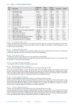
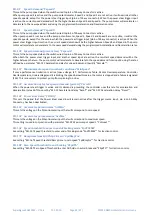
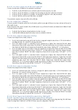
The status menu shows various parameters from the controller which can be useful to help tune and optimize vehicle
’s
performance. By pressing the decrement ( ) or the increment (
) button on the calibrator extra information about the
selected status variable are displayed.
Cal.
Ref.
Item
Calibrator text Step size Service log info & Notes
1
Drive hours counter
Drive
0.1 Hrs
shows key hours
2
Current Fault code
CurFault
Fxx
Show fault time
Sub code
3
Battery Discharge
Indicator
BDI
1 %
Raw BDI value incl.
state (WO & CO)
BDI states
(see
)
4
Controller Temperature
CtrlTmp
0.1
C
Min. temperature
Max. temperature
5
Motor Temperature
MotTemp
0.1
C
Shows N/A when disabled.
Min. temperature
Max. temperature
6
Drive State
DriveSta
--
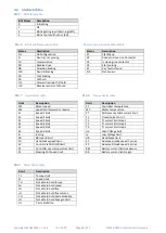
See
M2-6 Drive and brake status table
7
Speed Limit
SpeedLim
--
See
8
Torque Limit
TrqLimit
--
See
9
Motor Limit
MotorLim
--
See
10 Battery Voltage
BatVolts
0.1 V
Max. Voltage
11 Capacitor Voltage
CapVolts
0.1 V
Max. Voltage
12 Battery current
I_batter
0.1 A
13 Motor current
I_Motor
0.1 Arms
Id Current
Iq Current
14 Motor voltage
V_Motor
0.1 Vrms
Reactive Power
Motor Power
Reached maximum
output voltage (VL)
15 Stator speed
StatorSpd
0.1 Hz
16 Rotor speed
RotorSpd
0.1 Hz
RPM speed
17 Accelerator demand
Accel
0.1 %
Steer pot demand
Foot brake demand
18 Target demand
DemTrgt
0.1 %
+
CW
−
CCW
19 Ramped demand
DemRampd
0.1 %
+
CW
−
CCW
20 Speed limit %
21 Drive torque limit
DrvTrqL
0.1 %
Torque limit CW
22 Brake torque limit
BrkTrqL
0.1 %
Torque limit CCW
23 Actual torque
TrqAct
0.1 %
Actual torque in
Nm
Maximum torque in
Nm
+
CW
−
CCW
24 Actual speed
SpeedAct
0.1 %
+
CW
−
CCW
25 Actual Flux
FluxDem
0.1 %
Actual Flux
26
Filtered capacitor
voltage
27 Vehicle Speed
Vehicle
1 Kph
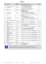
To reset the max and min temperatures logged data, press the
+
and
–
button at the same time when
the controller is in neutral.

