14 DiViS
®
w w w .
DiViS
D V R . c o m
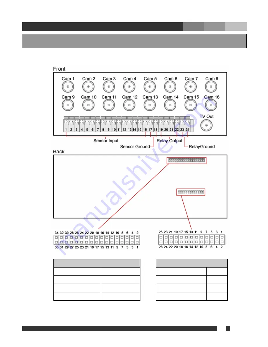
5-1. Back Panel
Sensor & Relay (Digital I/O)
Sensor Input 0~15
1~16
Input Common 0~1
17, 18
Relay Output 0~3
19~22
Output Common 0~1
23, 24
Camera I/O
Camera Ground
3, 5, ~ 31, 33
Camera Signal
4, 6, ~ 32, 34
TV Out Ground
1
TV Out Signal
2
5. Accessories


