background image

Part 2 - Configuration

36

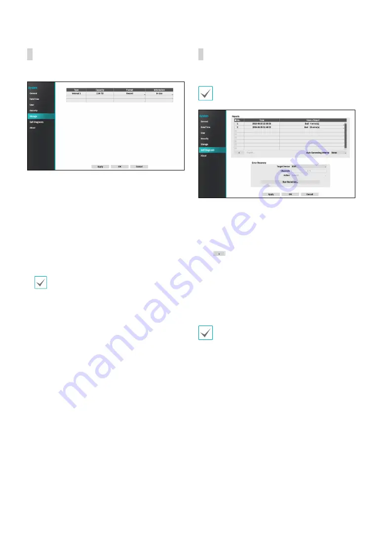
Storage

Use this option to configure storage settings.


Type

: Indicates the type of the installed disk.


Capacity

: Indicates the disk’s capacity.


Format

: If the disk has been formatted, indicates 

either 

Record

 or 

Not Using

. If you have connected an 

unformatted storage device, the Use As value will be 
indicated as 

Not Formatted

.


Information

: Indicates if the disk is being used for 

recording purposes. Disks that were used in different 
systems will show up as 

Other

. Select 

Information


to check the saved data’s time information or select 

Delete

 to erase the data.


Select 

Format

 to prepare the disk as a storage for 

data recording.


Disks formatted with Use As set to 

Not Using

 will 

not be used for data recording.


This NVR supports SATA2 HDDs.

Self-Diagnosis

Use this option to configure self-diagnostic settings.

This feature is also supported when connected to the 
NVR from a remote program.


Reports


No.

: Selects which reports to export.


Time

: Displays when you started the self-diagnosis. 


View a Report

: Briefly displays whether the report 

is “Good” or “Bad”. 


Click the + icon at the bottom left corner of 

the screen to run the self-diagnosi

.


Export

: Saves the Saves the reports to a storage 

device (USB port), by converting them to HTML 
format. You can export more than one report at a 
time by selecting multiple reports. 


Auto Generating Interval

: Select any time period 

between 6 hours and 7 days.


The reports are stored in up to 24 files. If you have 
configured 

Auto Generating Interval

 as one-day 

period, only the the reports from the last 24 days 
can be viewed.


If the NVR is turned off, the reports will 
automatically turn off.


The reports are organized by recent date and time.


FailOver: 

Whene a problem is detected on the target 

device, click the 

Run the failover button

 to resolve 

the problem.


Target Device.

: Selects which device to run the 

failover.


Channels

: Select the camera channel if a camera is 

set to the target device.


Action

: Select the type of action to run the failover.


Run the failover

: Click the 

Run the failover 

button when a fail is detected on the target device 
to resolve the problem.

Summary of Contents for IDIS DR-1304P

Page 1: ...Powered by Network Video Recorder Operation Manual DR 1304P DR 1308P DR 1304PC ...

Page 2: ... and use If you need to disassemble the product for functionality expansion or repair purposes you must contact your retailer and seek professional assistance Both retailers and users should be aware that this product has been certified as being electromagnetically compatible for commercial use If you have sold or purchased this product unintentionally please replace with a consumer version Safety...

Page 3: ...ing instructions adjust only those controls that are covered by the operating instructions as an improper adjustment of other controls may result in damage and will often require extensive work by a qualified technician to restore the equipment to its normal operation E If the equipment has been dropped or the cabinet damaged F When the equipment exhibits a distinct change in performance this indi...

Page 4: ...E INTERFERENCE AT THEIR OWN EXPENSE WARNING CHANGES OR MODIFICATIONS NOT EXPRESSLY APPROVED BY THE PARTY RESPONSIBLE FOR COMPLIANCE COULD VOID THE USER S AUTHORITY TO OPERATE THE EQUIPMENT THIS CLASS OF DIGITAL APPARATUS MEETS ALL REQUIREMENTS OF THE CANADIAN INTERFERENCE CAUSING EQUIPMENT REGULATIONS WEEE Waste Electrical Electronic Equipment Correct Disposal of This Product Applicable in the Eur...

Page 5: ...d We are not responsible for any problems resulting from the use thereof The information contained herein is subject to change without notice Revisions or new editions to this publication may be issued to incorporate such changes The software included in this product contains some Open Sources You may obtain the complete corresponding source code depending on whether or not the source is publicly ...

Page 6: ...s 20 Diagnosis Process 21 Camera Registration Mode 21 Login 22 Live Menu 24 Zoom 26 PTZ Control 26 Dewarping Control Camera 28 Event Monitoring 28 Covert Camera 28 Context Menu Access 28 Edit Group 29 Video Recording 29 Panic Recording 29 Video Recording Playback 29 All Channel Playback 29 Part 2 Configuration 30 Menu Use 30 Text Input via Virtual Keyboard 30 Batch Assignment 31 Mouse 31 System Se...

Page 7: ...eneral 49 Schedule 50 Pre Event 52 Event Setup 52 System_Event 52 Camera System 53 Camera System_Video Loss 54 Camera System_Recording Fail 54 Video Analytics 55 Video Analytics_Motion 55 Video Analytics_Trip Zone 57 Video Analytics_Tampering 58 Network Setup 59 General 59 WLDLWAN 59 FEN 61 Firewall 62 Notification Setup 62 Schedule 62 Callback 63 Mail 63 Push 64 Display Setup 65 OSD 65 ...

Page 8: ...us Setup 66 Camera 66 Device 66 System 67 Storage 67 Network 68 Part 3 Search 70 Time Lapse Search 70 Search Menu 70 Context Menu 72 Motion Search 72 Clip Copy 73 Event Log Search 74 Overlapped Recording Search 75 Memo 76 3 ...

Page 9: ...lick the question mark button on the bottom left corner and refer to the instruction on setting up a password An email address and UPR files are required to find the password Otherwise you may not be able to find your password when you enter the incorrect information Setup Wizard Setup Wizard lets you configure basic settings required for operating the system Setup Wizard only appears during initi...

Page 10: ... settings refer to the Date Time section under System Setup on page 30 3 Choose the desired Recording Method and click Next 4 Choose the desired Recording Quality and click Next Higher recording quality uses up more disk space Recording resolution is determined based on the selected recording quality High Video Quality Priority Profile Very high Standard Recording Profile High Longer Recording Tim...

Page 11: ...ord High Continuous Very high Motion Standard Continuous High Motion Low Continuous Standard Motion Continuous Very high High Low 5 Choose the desired codec and click Next 6 Click Finish to exit Quick Wizard Network Wizard After exiting from Quick Wizard the network with Network Wizard will start automatically 1 Select Network Wizard 2 Specify whether the system is connected to the Internet and cl...

Page 12: ...he router s UPnP function refer to the router s operation manual 4 Enter in the Device Name field the NVR name to be registered on the FEN server and then click Check to check its availability The device name you register on the FEN server will be a unique name used to identify the NVR Once registered the name can be used to access the NVR directly from clients such as the IDIS Center Check the na...

Page 13: ... mouse and select Camera Registration to run the Camera Registration mode It allows you to scan for the cameras connected to the NVR 1 2 3 4 5 1 Camera Scan Button 2 Camera View Menus 3 Camera List Area 4 Video Display Area 5 Apply Cancel Buttons You can also register cameras on the remote program For more information on the remote camera registration refer to Registration on page 13 ...

Page 14: ...a camera The NVR scans for the camera matching the specified address If you enter IP address s range the NVR scans for cameras falling under the specified address s range By specifying an IP address you can also specify which port to use with the Remote Admin feature It is recommended that the camera not be networked via DHCP Dynamic Host Configuration Protocol If the camera is networked via DHCP ...

Page 15: ...tes an IP address automatically in the range of 10 10 0 128 to 10 10 254 254 by using DHCP to the camera connected to the NVR s VIDEO IN port On DHCP Server Video In Network is connected between NVR and network cameras only so Gateway does not have any meaning Subnet Mask is 255 255 0 0 Class B When several NVRs exist in the same network only one of NVRs has to be run as a DHCP server If several D...

Page 16: ...sily Export Button Exports the list of camera information on USB as a csv file Import Button Imports a camera information file csv file The user can edit a csv file directly A column indicates camera number B column the camera MAC address C column the Video In port of the video encoder in the csv file C column indicates only for video encoders If camera information displays as follows 5 00 11 22 1...

Page 17: ... registered bitrates may not be lower than current stream settings When selecting default performance is evenly assigned to each channel If a channel has a camera already registered the minimum value is assigned Tool Button Displays network camera tool window to run a camera related actions There are Authentication Screen Assignment and Camera Protocol Change for actions 1 Select an Action to exec...

Page 18: ...ra list entry Add Remove Camera Adds or removes the selected camera The Add Camera option is inactive if the camera has already been added to the screen Authentication Enter the necessary camera login info This option is inactive for DirectIP IDIS cameras because they do not require logins This option is inactive for IDIS protocol only if the password is set Video Display Area Left click on the vi...

Page 19: ...ng up the camera menu Remove Camera Removes the registered camera Remove Device Removes the registered encoder Color Control Adjusts the camera s color settings Information Displays the camera s basic information Title Edits the camera s title Bitrates Changes the bitrate allocated to the channel Remove All Cameras Removes all registered cameras You can drag drop to add or remove cameras Apply Can...

Page 20: ...e new registered and changed cameras If Self diagnosis is processing Diagnosis Processing message will be displayed If Self diagnosis is failed Diagnosis Requirement message will be displayed In this case you can run Self diagnosis manually Camera Registration Mode While in Live mode right click and select Camera Registration ...

Page 21: ...word field using the mouse This will bring up a virtual keyboard you can use to assign a password For more information on using the virtual keyboard refer to the Text Input via Virtual Keyboard on page 29 3 To log out bring up the Live menu and click on Log out using the mouse Find Password If you do not know the password select FIND PW You can set a new password 1 Enter a user registered email an...

Page 22: ...le must be saved in advance For more information on saving the UPR file refer to User on page 33 You can reset the password using an encrypted UPR User Password Reset filename extension upr file It can be used as USB flash driver on local pc but not remotely Only files exported from the same device are available If you lose the UPR file and change the password of the NVR the UPR file may not be us...

Page 23: ...play the optimized video of the camera when using the camera s pivot feature This is particularly effective when monitoring hallways passages and other confined spaces 1 5 1 7 and 3x3 screen format are supported only on 8 channel model 3 Previous Next Group Loads the previous next screen group 4 Display OSD On Screen Display Enables disables the OSD feature Full Displays the video in full screen m...

Page 24: ... page numbers appear on the system status area on the upper right part of the screen next to the Sequence icon Pages are skipped under the following circumstances If all cameras included in the page are deactivated If there are no video signals If the page contains covert cameras If the user does not have permission to view feeds from the cameras 8 Select Camera Displays the selected camera in a s...

Page 25: ... activated icon is on the status bar located on the upper right corner of the system In Full Screen mode activating Zoom automatically selects the current channel To restore the channel to normal size press the Zoom button again PTZ Control While in Live mode right click and select PTZ from the context menu The icon will begin to flash on the selected camera s OSD window You can change the directi...

Page 26: ... This menu lists Speed Auto Pan and other advanced PTZ camera control options available for the camera Also selecting Point Move button moves PTZ camera to the point that the user clicks Options that are not available for the selected PTZ camera remain inactive You can use the mouse to control PTZ cameras Left click on the mouse and drag to move the camera in the desired direction and use the mous...

Page 27: ...R will return to the previous screen if a new event does not take place Pressing the Layout or a Camera button before the end of the Linked Time reverts the system to Live mode Covert Camera Use this feature to assign Covert Camera View permissions Navigate to Camera Setup General and designate cameras as Covert 1 or Covert 2 Covert 1 Hides images from the camera in Live mode but does indicate the...

Page 28: ...p Panic Recording select the Panic Recording icon again If the Panic Recording Duration option under Record Setup General has been configured Panic Recording will automatically terminate after the specified duration of time has elapsed For more information refer to the Record Setup on page 48 Panic Recording takes place irrespective of any recording schedule set up by the user Panic Recording vide...

Page 29: ...e in Live mode select Live menu Setup using the mouse 1 2 3 4 5 6 7 8 1 System Setup 2 Camera Setup 3 Record Setup 4 Event Setup 5 Network Setup 6 Notification Setup 7 Display Setup 8 Status Setup 2 Left click on the option using the mouse 3 Change the setting and then select Apply or OK to save the change To apply default settings select the Default button located on the left bottom corner of the...

Page 30: ...ter a description about the system s installation site no description by default You can edit the information using the virtual keyboard System ID Used to identify the NVR apart from other NVRs The default System ID is 0 and can be changed to a value between 0 and 99 The System ID can also be entered using the virtual keyboard Language Choose a language Version Indicates the software version Upgra...

Page 31: ...entries For more information on types of system log entries refer to the System Log Types in the installation manual The icon appears next to log entries originating from a remote source To export the system log select the Export at the bottom of the screen and then designate a file name In order to display the system_log txt file you must use the correct character encoding settings and use a fixe...

Page 32: ...ze with 1 Select Automatic Sync 2 Enter the Time Server s IP address or domain name or select and then choose a server from the list of registered time servers 3 Specify the server synchronization Interval 4 Select OK to apply and exit If you have configured the DNS Server setting under Network WAN you can enter the time server s domain name instead of its IP address Holiday Designate holidays On ...

Page 33: ...elect OK 7 Configure Auto Login and Auto Logout settings 8 Select Apply or OK to exit Group names user names passwords and email can be entered using the virtual keyboard For more information on using the virtual keyboard refer to the Text Input via Virtual Keyboard on page 29 To delete a registered user or group select the icon on the right of the corresponding user group Group Administrator and ...

Page 34: ...ll its initial factory settings Search Clip Copy The user who has permission for Clip Copy can perform Clip Copy If the user does not have permission Clip Copy is not allowed but only search is allowed Setup Camera Setup May configure camera settings System Time Change May change the system s date and time settings Data Clear May clear data stored in the system PTZ Setup May configure PTZ settings...

Page 35: ...ister the following message will appear 2FA device registration is supported only via IDIS Mobile app Only the administrator account user can configure this option The maximum number of device that can be registrated is 16 When the mobile device registration is complete the following message will appear Click Disable 2FA at the bottom left corner of the screen to deactivate 2FA function via the em...

Page 36: ...t Time Displays when you started the self diagnosis View a Report Briefly displays whether the report is Good or Bad Click the icon at the bottom left corner of the screen to run the self diagnosi Export Saves the Saves the reports to a storage device USB port by converting them to HTML format You can export more than one report at a time by selecting multiple reports Auto Generating Interval Sele...

Page 37: ...ee the brief results of the self diagnosis for the target device The NVR self diagnostic report can only be viewed in text form This feature is also supported when connected to the NVR from a remote program We recommend clicking the Export button at the bottom of the list which allows you to view the reports on a PC web browser We also recommend scanning the self diagnostic report on a remote prog...

Page 38: ...on about supported network devices and models contact your retailer The supported scan modes may vary depending on protocol selected Mode Select the scan mode Auto Scan LAN Lists any cameras in a LAN environment If Auto scan LAN fails to recognize the camera try using IP Address scan instead IP Address Enter the IP address of a camera The NVR scans for the camera that matches the specified address...

Page 39: ...selecting Apply to All Devices you can apply the same authentication information to all of the network devices in the list When you select multiple network devices from the list and click the Add camera button a window for the network device will appear Select Skip to skip the authentication settings for the current network device and to display the Authentication window of the next network device...

Page 40: ...It is not supported by video encoders Soft Reset Reboots the camera Factory Reset Resets the NVR to all its initial factory settings It is supported by DirectIP cameras only Mode Select a resolution mode This is supported by video encoders only 1 2 3 4 5 6 7 8 9 0 Numbers shown below Preset Scan Pattern and Tour indicate the numbers of configured functions 1 Preset Use the buttons below to choose ...

Page 41: ...cording Select a pattern number enter a name for the pattern and then click OK to save the pattern Move the camera using directional zoom and focus buttons and then click Stop recording to save the pattern profile You can record up to two minutes of movement Directional Buttons Used to tilt and pan the camera Zoom Zoom in and out Focus Adjust camera focus to far or near Speed Specify the camera s ...

Page 42: ...When Auto Pan is selected from a remote program the camera pans in the direction selected here 9 Auto Flip Automatically flips the image when the camera tilts past 90 to prevent the objects from appearing upside down Digital Flips the image left to right or top to bottom Mechanical Automatically pans or tilts the camera Off Disables Auto Flip 0 Tilt Range Specify the camera s tilting range Restore...

Page 43: ... disable IR Mode automatically Schedule Set up the IR Mode schedule IR Mode is disabled for all days and times that are designated as Daytime in the schedule and is enabled at all other times Some camera models may not support the Schedule function White LED Mode Clicking on off enables or disables White LED lighting when motion is detected by the PIR sensor Also clicking auto allows the system to...

Page 44: ...e is changed under high lighting conditions Also the lower the value is day nighttime mode is changed under low lighting conditions Mirror Select Horizontal or Vertical to flip the image horizontally and or vertically Select Apply after setting up a camera to see images from the concerned camera on the left side of the screen Selecting Apply or OK displays a popup screen that indicates whether the...

Page 45: ...focus movement format as Auto Manual Semi Automatic It may not be supported depending on the device WDR Disables or enables the WDR Wide Dynamic Range When the very dark and very bright areas exist simultaneously on the screen WDR allows you to recognize the both areas IRIS Depending on the camera type the user can select DC IRIS or P IRIS DC IRIS OFF Select this if a manual IRIS lens is mounted o...

Page 46: ...Apply the video profile settings of the camera selected under Camera Channel to a different camera Live Remote Video Profile Check the current Live video picture quality and edit remote video profile settings Record Video Profile Set up 4 recording quality profiles Video Profile Select Stream 1 Stream 2 Stream 3 or Custom available from Record Video Profile only Codec Supports H 264 and H 265 Reso...

Page 47: ...n function is active the associated VA device may not work properly It is recommended that you do not use the MAT function of the associated camera to increase the accuracy of the image analysis Some camera models may not support the MAT function MAT function Motion Adaptive Transmission reduces bandwidth overload and saves storage capacity by reducing the frame rate of the video during periods of...

Page 48: ...recording is designated as an event triggered action recording takes place for the duration specified under this setting Auto Deletion Configure this option to delete recording data automatically after the specified number of days has elapsed Select between 1 day and 999 days To disable Auto Deletion select Never If enabled recording data will be stored on the NVR for the specified number of days ...

Page 49: ...ecording automatically Select between 5 mins and 1 hr If you do not wish to disable the feature automatically select No Limit Video Profile Select a recording profile value for Panic Recording Schedule Simple Mode Advanced Mode Disabling Schedule On suspends schedule recording regardless of the schedule and displays the icon on the upper left corner of each camera screen Pressing the Panic Record ...

Page 50: ...and recording commences as per the video profile selected for time under Setup When an event occurs the icon changes into icon and recording commences as per the video profile selected for events under Setup Channel Select which cameras to apply the schedule to Settings Select to configure default recording profile values for Time Lapse and Event Recording modes Advanced Mode Options Select to con...

Page 51: ...nt recording data If no event mode schedule exists in the schedule a warning message prompting you to add an event mode schedule will be displayed The warning message will appear even in Time Event mode Event Setup Refer to the Menu Use on page 29 for basic information on using the Setup menus System_Event Use this option to configure system event settings Settings Configure when and what the syst...

Page 52: ...ll disks reach their maximum capacity Disk Bad Generates an event when the specified percentage of the disk becomes damaged Set to between 10 and 90 in 10 intervals Disk Temperature Specify the threshold temperature Once any disk reaches this threshold the system will issue an alert Disk S M A R T Monitors disks that support S M A R T and notifies the user if a disk error is detected Disk Config C...

Page 53: ...r the time specified after the initial video loss was detected Set the value between 0 1 and 15 seconds or choose Never This is supported only when video encoders are connected Use Ignoring Time Select Time Setup to specify the time to ignore video loss detection Video loss detection will be disabled for a specified time period This is supported only when video encoders are connected Camera System...

Page 54: ... reverse the selection From the zone selection screen right click on the mouse to open up the Zone Setup menu Select Confirm the block selection in the selection window Clear Clear the block selection in the selection window Reverse Clear the blocks selected within the selection window and select all unselected blocks within the selection window Select All Select all blocks rmn Clear All Clear all...

Page 55: ...onfigure to be notified of events by Mail LAN1 through 5 Push and or Alert Window PTZ Moves the PTZ camera to a specific preset position when an event occurs Event Monitoring Selects the cameras to monitor when an event occurs In order to use the Callback feature the NVR must be registered on the remote program Ignoring Interval The system does not produce event log entries or issue remote notific...

Page 56: ...ar Clear the block selection in the selection window Reverse Clear the blocks selected within the selection window and select all unselected blocks within the selection window Select All Select all blocks Clear All Clear all block selections Reverse All Clear all selected blocks within the screen and select all unselected blocks within the screen Trip Direction Define in which direction the motion...

Page 57: ...t the time frame in 15 minute increments Times outside the specified range will be assumed as nighttime by the system Video Analytics_Tampering No Select which cameras to apply Tampering to Sensitivity Set to between 1 Low and 5 High Activation Time Specify how long tampering detection needs to last in order for it to be considered an event Tampering detections that do not last for the specified d...

Page 58: ...ed by OpenSSL Project for use in Open SSL Toolkit http www openssl org Network Bandwidth Limit Configure the bandwidth limit If you configured Network Bandwidth Limit the live video may not display smoothly in a remote program WLDLWAN Designate the IP address type as Manual or DHCP Manual Set Type to Manual Manual lets you configure related settings manually Configure IP Address Gateway and Subnet...

Page 59: ...dress In order to use the UPnP service the IP router or NAT must support UPnP port forwarding and have the relevant options enabled Port number cannot be changed with Use UPnP selected Status Indicates the number of the port forwarded by the IP router or NAT to the NVR via UPnP service DHCP Select DHCP and then Save to retrieve IP address and other network settings automatically from the DHCP serv...

Page 60: ...leave the FEN name blank it automatically changes to the default name FEN Server Enter the FEN server s IP address or domain name If you have configured the DNS Server setting under Network WAN you can enter the FEN server s domain name instead of its IP address in the FEN Server field Port Specify the FEN server s port number If using an IP router or NAT port configuration and other network funct...

Page 61: ...y the ethernet interface It refers to a WAN Network Client or VIN Video In Mac Address If the rule is set to MAC address enter the sending MAC address IP If the type of the rule is set to IPv4 or within the IPv4 scope enter the sending IP address Port If the type of the rule is set to port or within the port scope enter the receiving network port number of NVR Notification Setup Schedule Select th...

Page 62: ... will attach the event detected image file MP4 format to an email Mail Add a mail recipient Select the group name and then assign the Group to Recipient Enter the the recipient s e mail address and mail server provider Select the icon to select the mail server provider from a list ot registered SMTP mail server providers The recipient s mail address must be in the correct email format and contain ...

Page 63: ... WAN you can enter the STMP server s domain name instead of its IP address in the SMTP Server field Address entered under Sender must be in the correct email format and include the symbol If user authentication is required by the SMTP server select Use and then enter the User and Password information 3 Select OK to apply and exit This product contains content developed by OpenSSL Project for use i...

Page 64: ...ence refer to the 7 Sequence on page 23 Manual Configuration Set the resolution manually regardless of the resolution supported by the monitor Resolution Select from 1920 x 1200 1920 x 1080 1680 x 1050 and 1600 x 1200 Event Monitoring On With Event Monitoring enabled the camera screen linking event monitoring is shown For more information on Event Monitoring refer to the Event Monitoring on page 2...

Page 65: ...a This screen displays an overview of camera events When an event occurs the corresponding channel flashes for 5 seconds Event Types Motion Trip Zone Tampering Video Loss Device This screen displays an overview of device events When an event occurs the corresponding channel flashes for 5 seconds Event Types Recording Fail ...

Page 66: ...Full Disk Full If the storage device is not in Recycle status event status is displayed when the amount of disk space specified under System Monitoring is reached and when the disk becomes 100 full For more information refer to the Self Diagnosis on page 36 Disk Config Change It will be highlighted when the NVR reboots after the hard disk drive has been replaced No Storage Found It will be highlig...

Page 67: ...ure higher than as designated by the user Generates a system event S M A R T N A A disk that does not support S M A R T Good A disk with normal S M A R T status Bad A disk with abnormal S M A R T status Possibility of damage within 24 hours Check each disk s data storage time information under Recording Data Clicking the temperature S M A R T can check the each HDD information Network This page pr...

Page 68: ...he image displays status information of the device connected to the NVR LAN Port Link indicates a camera or a network switch is connected indicates neither is connected Power Consumption If receiving power from the NVR the actual amount of power consumed by each camera is indicated under each camera icon Total power consumption is shown at the top of the screen in the following format TotalPoEPowe...

Page 69: ... icon to add a bookmark to the current playback position Select a bookmark from the Bookmark setup window on the right side of the Time Lapse Search mode screen to move to the registered playback position Select Bookmark list and then the icon to delete the corresponding bookmark The maximum number of bookmarks that can be saved is 12 2 Playback Controls Play and scan through video recordings Jog ...

Page 70: ... indicator line on Record Table indicates the current playback position Alternatively use the mouse to jump to the desired playback position Farther back the data is on the record table the more recent it is If the system s clock is changed to a previous date and time it is possible for multiple recordings with the identical time stamp to exist Overlapped segments are highlighted in yellow Selecti...

Page 71: ... movements no matter how long they persist will not be recognized In contrast Museum Search looks for changes in the specified area by using the From frame as a reference Museum Search therefore recognizes even minute deviations from the original From frame The Zone setting can be configured in the identical manner as the Zone setting under System Setup Motion Detection For more information refer ...

Page 72: ...ground Selecting Close does not cancel Clip Copy Once the process is complete you will be prompted with a confirmation window Click Export ClipPlayer button to save the clipplayer exe file playing CBF files to USB One Touch Clip Copy configures the storage range automatically based on the storage drive s capacity If there is insufficient space available on the selected storage device you will only...

Page 73: ...els to search Exceed the Time Limit events in If the system s clock has been changed and the designated From or To point exists at more than one location you will have to choose one Only the events that took place between the selected From and To points will be searched If Check Time Overlap has not been selected events from the entire From and To range will be searched Use event filters to includ...

Page 74: ...5 00 6 00 Segment 1 Segment 2 When searching overlapped video recordings you can choose a specific point in time or a time frame If you use the Go to the Date Time option and select a point within the overlapped time period 4 o clock for example you must specify 4 o clock in which of the two existing segments If you use the Event Log Search or Motion Detection option and select a time frame within...

Page 75: ...Part 3 Search 75 Memo V5 8 ...

Page 76: ...IDIS Co Ltd For more information please visit at www idisglobal com ...

Reviews: