Q U I C K S T A R T G U I D E
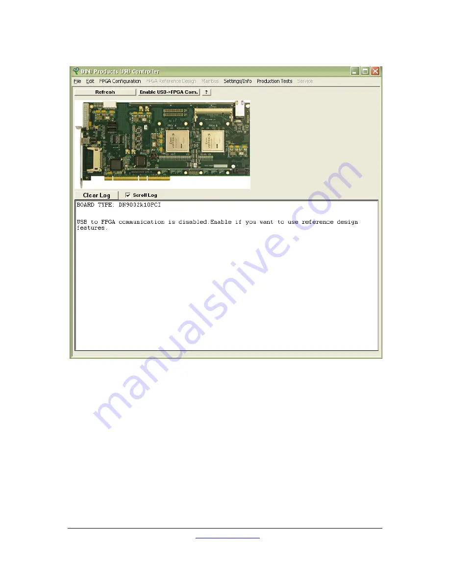
Figure 5 USB Controller Window
This window will appear showing the current state of the DN9002K10PCI. Next to each
FPGA a green light will appear if that FPGA is configured successfully. The above window
shows the USB Controller connected to a DN9002K10PCI with two LX330 FPGAs.
5.2.1
Configure an FPGA
Even though the reference design should already be loaded (because you had a CompactFlash
card installed when the board powered on), let’s configure an FPGA over USB.
Clear an FPGA of its configuration. Right-click on an FPGA and select from the popup menu,
“Clear FPGA”. The blue light above the FPGA on the GUI and on the board should turn off.
To re-configure that FPGA using the USB Controller program, right-click on the FPGA and
select Configure FPGA via USB from the popup menu. The program will open a dialog box for
DN9002K10PCI User Guide
www.dinigroup.com
16
Summary of Contents for DN9002K10PCI
Page 1: ...LOGIC Emulation Source UserGuide DN9002K10PCI ...
Page 3: ......
Page 34: ......
Page 46: ...C O N T R O L L E R S O F T W A R E DN9002K10PCI User Guide www dinigroup com 36 ...
Page 150: ......


