background image

DNDS Modular     Original Betriebsanleitung      Original Instruction Manual


Sicherheitstechnik  Stand 19.02.2018 


Date 2018-02-19 


Seite 5 von 31 

page 5 of 31 


Sicherheitsbestimmungen 


Das Gerät darf nur von einer Elektrofachkraft oder un-

terwiesenen Personen installiert und in Betrieb  
genommen werden, die mit dieser Betriebsanleitung 
und den geltenden Vorschriften über Arbeitssicherheit 
und Unfallverhütung vertraut sind.  


Beachten Sie die VDE- sowie die örtlichen Vorschriften, 

insbesondere hinsichtlich der Schutzmaßnahmen. 


Werden die Sicherheitsvorschriften nicht beachtet, 

kann Tod, schwere Körperverletzungen oder hoher 
Sachschaden die Folge sein. 


Bei Not-Halt-Anwendungen muss entweder die  

integrierte Wiedereinschaltsperre Funktion verwendet 
werden oder der automatische Wiederanlauf der  
Maschine muss durch eine übergeordnete Steuerung 
verhindert werden. 


Halten Sie beim Transport, Lagerung und im Betrieb die  

Bedingungen nach EN 60068-2-1, 2-2 ein! Siehe  
technische Daten! 


Durch eigenmächtige Umbauten erlischt jegliche  

Gewährleistung. Es können dadurch Gefahren entste-
hen, die zu schweren Verletzungen oder sogar zum Tod 
führen. 


Montieren Sie das Gerät in einem Schaltschrank mit 

einer Mindestschutzart von IP54! Staub und Feuchtig-
keit können sonst zu Beeinträchtigungen der Funktio-
nen führen. Der Einbau in einem Schaltschrank ist 
zwingend notwendig. 


Sorgen Sie für ausreichende Schutzbeschaltung an  

Ausgangskontakten bei kapazitiven und induktiven 
Lasten!  


Das Gerät ist unter besonderer Berücksichtigung der 

nach DIN EN 50274, VDE 0660-514 geforderten  
Abstände einzubauen.  


Während des Betriebes stehen Schaltgeräte unter ge-

fährlicher Spannung. Schutzabdeckungen dürfen wäh-
rend des Betriebes nicht entfernt werden. 


Wechseln Sie das Gerät aus nach dem ersten Fehlerfall 

unbedingt! 


Entsorgen Sie das Gerät nach Ablauf der Lebensdauer 

sachgerecht! 

+

-


Bei nicht Einhaltung dieser Vorschriften, akzeptiert  

DINA Elektronik GmbH keinerlei Ansprüche für die  
Entstehung von Personen oder Sachschaden. 


Bewahren Sie diese Produktinformation auf! 

Safety regulations 


The device may only be installed and commis-

sioned by an  electrician or trained persons who 
are familiar with these operating instructions and 
the applicable regulations regarding work safety 
and accident prevention.  


Observe the VDE, EN and local regulations, particu-

larly with respect to the protective measures.  


Failure to observe the regulations may result in 

death, severe bodily injury or extensive property 
damage.  


For emergency-stop applications, either the inte-

grated function for restart interlock must be used 
or automatic restarting of the machine must be 
prevented by means of a higher-level control.  


During transport, storage and operation adhere to 

the conditions specified in EN 60068-2-1, 2-2!  


Unauthorized modifications shall render any  

warranty null and void. Dangers may thereby arise 
that could result in severe injuries or even death.  


Install the device in a control cabinet with a  

protection class of at least IP54! Dust and mois-
ture may otherwise result in impaired functions.  
Installation in a control cabinet is mandatory.  


Ensure adequate protection circuits at output con-

tacts for capacitive and inductive loads!  


The device is to be installed taking into account 

the distances required per DIN EN 50274, VDE 
0660-514.  


During operation, switching devices carry danger-

ous voltage. Do not remove protective covers.  


Replace the device after the first malfunction!  


Properly dispose of the device at the end of its  

service life. 

+

-


If these regulations are not adhered to or in the 

event of improper use, DINA Elektronik GmbH  
accepts absolutely no liability for the resulting 
property damages or personal injury.  


Save this product information! 
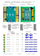
Summary of Contents for DNDSmodular

Page 1: ...Original Betriebsanleitung Original Instruction Manual Metallgeh use Kunststoffgeh use Metal housing Synthetically housing Wir sind Sicherheit We are safety...

Page 2: ...utilizan los siguientes est ndares e DIN EN 60947 5 1 2015 05 f DIN EN ISO 13849 1 2016 06 g DIN EN ISO 13849 2 2013 02 Zusatzanforderung Supplementary requirements DGUV Test GS ET 20 2016 10 DIN EN...

Page 3: ...hler und St rungen 12 Faults and Errors 12 Reaktionszeit 12 Reaction times 12 Inbetriebnahme 13 Operation 13 Wiedereinschaltsperre S4 Position 1 und 2 on 13 Restart interlock S4 position 1 and 2 on 13...

Page 4: ...EN 60947 5 1 Part 5 2010 4 Low voltage switch gear and control gear electro mechanical control circuit devices DIN EN ISO 13849 1 2016 06 Safety related parts of control systems Part 1 General princi...

Page 5: ...sten Fehlerfall unbedingt Entsorgen Sie das Ger t nach Ablauf der Lebensdauer sachgerecht Bei nicht Einhaltung dieser Vorschriften akzeptiert DINA Elektronik GmbH keinerlei Anspr che f r die Entstehun...

Page 6: ...Jahr bei Performance Level d angefordert werden Die Angaben in den technischen Daten am Ende dieser Betriebsanleitung m ssen beachtet werden Die Vorschriften des Herstellers der Anlage oder Maschine...

Page 7: ...ion Indicators and alarms Muting and temporary disabling of the safety functions Operation mode s general descriptions Maintenance Checklists and internal spare parts not valid Tools for easy and safe...

Page 8: ...4 3 2 1 5 6 on Modulf hrung Moduleguideway Einstellung am Rack Adjustment at the rack DNDS OM PM PMG GM V1 GMG V1 VM VMG on 6 5 4 3 2 1 DNDS GM GMG Modul links vom GM GMG steuert SPEED2 Module left o...

Page 9: ...IN1 und IN2 am Eingangsmodule angeschlossen Die Montage der Sensoren muss sicherstellen dass im Stillstand mindestens ein Sensor aktiv ist Statusanzeige ber LED Auswahl der max Drehzahlen erfolgt ber...

Page 10: ...inals reduction of the selection at D Terminals 100 25 Switch over between automatic mode Fx at 24V and tool setting function mode F off R1 Terminal To select the semi automatic mode R1 Terminal is on...

Page 11: ...9 on Teiler an 1 8 x 4 S1 S2 P10 off Messsystemfrequenz 50Hz unterdr ckt Einkanalige Messsystemfrequenz 800Hz ist unterdr ckt S1 S2 P10 on Messsystemfrequenz 25Hz ist unterdr ckt Einkanalige Messsyste...

Page 12: ...e divisor For resolver the change of the phase is monitored For incremental system monitored frequency for tool setting 10 20 moni tored frequency for standstill Nicht ben tzte berwachung F r den nich...

Page 13: ...DC Necessary F Terminals connected to 24V via control switch Automatic mode with Input modules with D Terminals only Necessary D Terminals connected to 24V via control switch Tool setting SH Terminal...

Page 14: ...S3 Position 3 4 ON Teiler variabel ON Divisor variable S3 Position 3 4 Off Teiler konstant Off Divisor constant S4 Position 1 2 ON Wiedereinschaltsperre aktiv ON restart interlock active S4 Position...

Page 15: ...minals 24V S6 S7 1 5 2 6 3 7 4 8 1 5 2 6 3 7 4 8 D1 D2 D3 D4 Hz F1 F2 F3 F4 00 100 5Hz 01 150 25 02 200 30 03 275 35 04 355 40 05 400 45 06 450 50 07 500 55 08 550 60 09 630 65 10 700 70 11 800 75 12...

Page 16: ...r Halbautomatikbetrieb und Einrichtbetrieb Siehe Tabelle unten Adjustment of the monitoring Frequency for semi automatic function mode and Tool setting see table down S4 Position 1 2 ON Wiedereinschal...

Page 17: ...5 50 237 59 2 4 5 12 28 100 475 60 2 42 7 17 29 20 110 61 2 50 10 25 30 5 5 50 275 62 2 53 15 38 31 100 550 63 600 Frequenzauswahl f r Vmax bei V7A und V7C Selection of frequency for Vmax using V7A an...

Page 18: ...Geschwindigkeit Selected maximal speed 24V Verbunden mit 24V DC Connected to 24V DC 33 3443 44 ffnen sofort bei V Vmax Open directly at V Vmax 57 5867 68V1 ffnen bei V Vmax nur wenn nach 0 5s V 90 vo...

Page 19: ...11 50 43 180 11 22 43 7 5 12 125 44 450 12 24 44 7 5 13 240 45 200 13 26 45 7 5 14 40 46 500 14 28 46 7 5 15 100 47 15 30 47 7 5 16 250 48 300 16 32 48 7 5 17 480 49 17 34 49 7 5 18 65 50 360 18 36 5...

Page 20: ...der berwachungsfrequenz f r Halbautomatikbetrieb und Einrichtbetrieb Siehe Tabelle unten Adjustment of the monitoring Frequency for semi automatic function mode and Tool setting see table down S4 Posi...

Page 21: ...Vmax Gew hlte maximale Geschwindigkeit Selected maximal speed 24V Verbunden mit 24V DC Connected to 24V DC 33 3443 44 ffnen sofort bei V Vmax Open directly at V Vmax 57 5867 68 V1 ffnen bei V Vmax nur...

Page 22: ...31 28 1 70 25 63 Frequenz Auswahl f r Vmax bei 1R 1RG V2 V3C Selection of Frequency for Vmax using 1R 1RG V2 V3C Auswahl von Vmax im Einricht und Halbautomatikbetrieb Auswahl von Vmax Selection of Vm...

Page 23: ...SPEED1 33 34 43 44 close directly if V 90 of Vmax LED right is green Usage start of the brake action of the drives See restart interlock LED at PMG PM LED left and right are dark without measuring sys...

Page 24: ...in case of fault the delay time can be shortened or the contacts open at once All contacts close again 57 58 67 68 with 250ms time delay if at all input modules V 90 of Vmax Terminals E1 E2 and Q con...

Page 25: ...1 13 12 14 21 23 22 24 68 67 58 57 E1 E2 Q 24VDC Not Halt Kreis Emergencystop circuit Schutzt rschalter Protectioncover switch Quit Maschinennetz Machinenet Netz Net T r entriegeln Cover unlock STOP S...

Page 26: ...GM GMG V1 0V STOPSPEED UB 68 67 58 57 24 23 14 13 SPEED2 STOP A1 33 34 43 44 SPEED1 A2 24V DC A1 24V DC 0 5A A2 0V DINAELEKTRONIK D 72649WOLFSCHLUGEN ID No 10GM0 DNDSGM 1ZD7 USLISTED IND CONT EQ R L U...

Page 27: ...0 von Vmax V nach 0 5s gr er 90 von Vmax V during 0 5s less than 90 of Vmax V after 0 5s bigger than 90 von Vmax V 100 60 V 90 Vmax 33 34 43 44 57 58 67 68 40 20 t tr V 100 60 33 34 43 44 57 58 67 68...

Page 28: ...3 F2 F2 F1 F1 F3 F4 F4 IN1 IN2 D1 D1 D2 D2 D3 D3 D4 D4 R1 SH 1 5V 1VSS 1Vpp 300KHz SPEED STOP ON verriegelt locked entriegelt unlocked 104mm Metall Metal Kunststoff Synthetically Rack Varianten Gewich...

Page 29: ...tern Minimal 1 25A Maximal Leitungsschutz Betriebstemperatur DIN IEC 60068 2 3 10 60 C Lagertemperatur DIN IEC 60068 2 3 40 85 C H henlage des Einsatzes 2000m ber NN R ttelfestigkeit in allen 3 Ebenen...

Page 30: ...tion Operating temperature DIN IEC 60068 2 3 10 60 C Storage temperature DIN IEC 60068 2 3 40 85 C High of the usage location 2000m over sea level Vibration tolerance on all 3 levels Sinus 10 55Hz 0 3...

Page 31: ...Instruction Manual Sicherheitstechnik Stand 19 02 2018 Date 2018 02 19 Seite 31 von 31 page 31 of 31 wir sind sicherheit DINA Elektronik GmbH Esslinger Str 84 D 72649 Wolfschlugen Phone 49 7022 9517...

Reviews: