DNDS Modular Original Betriebsanleitung Original Instruction Manual
Sicherheitstechnik Stand 19.02.2018
Date 2018-02-19
Seite 26 von 31
page 26 of 31
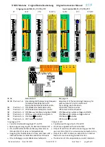
DNDS GMG, GM/ DNDS GMG, GM V1: Ausgangsmodule
DNDS GMG, GM/ DNDS GMG, GM V1: Output modules
Ausgangskontakte an
DNDS GMG/ GM
Contact outputs at
DNDS GMG/ GM
GMG, GM
GM
GMG V1
GMG V1
•
Stillstandsüberwachung
•
STOP: 13-14/ 23-24
offen bei Bewegung, LED
links dunkel,
geschlossen im Stillstand,
LED links grün.
Einsatz: Verriegelung einer
Schutzeinrichtung im Au-
tomatikbetrieb
•
Drehzahlüberwachung
•
SPEED1: 33-34/ 43-44 öff-
nen sofort bei V>Vmax.
LED rechts ist dunkel.
schließen sofort bei V<
90% von Vmax, LED rechts
ist grün.
Einsatz: Start des Brems-
vorgangs der
Antriebe
Siehe auch Wiederein-
schaltsperre.
•
SPEED2: 53-54/ 63-64
Siehe SPEED 1.
•
Dieses Modul ermöglicht
die Teilung des Antriebs-
verbunds in zwei Kreisen.
•
Standstill monitoring
•
STOP: 13-14/ 23-24
open during movement,
LED left is dark
closed during standstill,
LED left is green.
Usage: interlocking of a
safe cover during the au-
tomatic function mode.
•
Speed monitoring
•
SPEED1: 33-34/ 43-44 open
directly if
V>Vmax. LED right is dark.
SPEED1: 33-34/ 43-44 close
directly if
V< 90% of Vmax, LED right
is green.
•
Usage: start of the brake
action of the drives
See also restart interlock.
•
SPEED2: 53-54/ 63-64
See SPEED1
•
This output module ena-
bles the splitting of the
drive circuit in two circuits.
•
GM / GMG
V1
0V
STOP SPEED
UB
68
67
58
57
24
23
14
13
SPEED2
STOP
A1
33
34
43
44
SPEED1
A2
24V
DC
•
A1
24V
DC
0.5A
A2
0V
DINA ELEKTRONIK
D-72649 WOLFSCHLUGEN
ID-No:10GM0
DNDS GM
1ZD7
US LISTED
IND.CONT.EQ
R
L
U
S
TOP
SPE
ED
1
SPEED
2
P.
D.
B3
00
D
C
1:
6A
D
C
13:
4A
AC1
: 6
A
AC1
5:
3
A
BG
-
P
R
U
FZER
T
ET 13012
Sicherheit geprüft
tested safety
44
43
34
33
24
23
14
13
64
63
54
53
A2
A2
A2
A2
A1
A1
A1
A1
DN
DS
M
OD
UL
AR O
UT
PUT
M
ODU
LE
ON
SPEED
STOP
•
GM / GMG
V1
0V
STOP SPEED
UB
68
67
58
57
24
23
14
13
SPEED2
STOP
A1
33
34
43
44
SPEED1
A2
24V
DC
•
•
Fehler und Störungen
LED links und rechts am Ein- und Ausgangsmodul dunkel.
Ursachen
:
Kein Messsystem.
Sensorfehler an Klemme IN1, IN2
LED links und rechts auf dem Ausgangsmodul blinken kurz
Ursachen
:
Ein Kontakt schließt oder öffnet nicht.
Faults and Errors
LED right and left at the in- and output module dark.
Reason
:
No measuring system
Sensor failure at the terminal IN1, IN2
LED left and right on the output module flash short:
Reason
:
A contact does not close or open.
Ausgänge parallel
Outputs parallel
Ausgänge seriell
Outputs serial
NOT-HALT
Kreis 1
44
43
34
33
13
14
23
24
L1
L2
DNDS
11 13
12 14
21 23
22 24
64
63
54
53
24V DC
NOT-HALT
Kreis 2
STOP
SPEED1
SPEED2
DNDS
CNC
Emergency
stop circuit 1
Emergency
stop circuit 2
Schutztürschalter
Protection cover
switch
Quit
Tür
entriegeln
Cover
unlock
NOT-HALT
Kreis 1
44
43
34
33
13
14
23
24
STOP
SPEED1
L1
L2
Tür entriegeln
DNDS
DNDS
Quit
Schutztürschalter
11 13
12 14
21 23
22 24
64
63
54
53
SPEED2
24V DC
CNC
N
OT-HALT
Kreis 2
Emergency
stop circuit 1
Emergency
stop circuit 2
Protection cover switch
Cover unlock


