


Manual & Remote Operation
To go to the previous settings press the
‘
O
‘ button (Switch S3).
Pressing the ‘
O
‘ button on the remote turns off the light & hea
t
settings. To resume press the ‘
I
’ button until the desired setting
is reached - see
Fig. 8
.
To increase or decrease the brightness of the flames, use the
dimmer button (Switch S4 on the fire or the
button on the
Remote Control). You can have any setting between full
brightness and the flames totally off. The heat setting will remain
the same.
To turn off the power the Standby Switch (Switch S1) must be
turned ‘OFF’.
Note :
Every time that manual mode is selected the previous
light and heat settings come on automatically.
Replacing the remote control
The new remote control must be set up as follows:
Press switch S1 to
ON
.
Press switch S2 to
AUTO
(see
Fig. 6
).
Press switch S3 to
O
for more than 3 seconds until all three
LED’s are on (see
Fig 7
).
Press the
‘
I
’
button on the remote control.
Now the heater has learned the serial number from the remote
control and will work with this remote control only (this procedure
is repeatable many times).
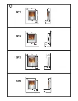
Instructions for fitting pebbles - SP8 only
The SP8 model is provided with a pebble fuel effect. To fit follow
the instructions given below.
Warning - The pebbles should only be placed on to the fuel
effect once the fire has been fully secured to the wall.
This should only be done when the appliance is switched
off.
The front panel will need to be removed in order to place the
pebbles on the fuel bed.
Warning -
The front panel is heavy and easily damaged.
1. Remove the two screws which hold the front panel in place -
see
Fig. 9
.
2. While holding the front by its sides with both hands carefully
tilt forwards and then lift
up
and
out
- see
Fig. 9
b.
3. Place the front panel flat on a protective surface such as a
matt with the glass facing away from the floor.
4. Remove the pebbles from the packaging and arrange on the
fuel bed.
5. Refit the front panel ensuring that its base is held in place i.e.
that it slots into the channel on the frame (see
Fig. 10
c) reversing
the steps as outlined previously.
Lamp Replacement
WARNING – ALWAYS DISCONNECT FROM THE POWER
SUPPLY BEFORE REMOVING LAMPS.
Warning -
The lamps reach high temperatures during operation.
For this reason, allow the lamps to cool down after switching off
the appliance.
The front panel will need to be removed in order to change lamps
– see
Fig. 9
.
Warning -
The front panel is heavy and easily damaged.
The front panel is fixed with two screws on top and is supported
underneath by the chassis see
Fig. 9
.
Care is needed to avoid the front panel falling forward while
removing the screws see
Fig. 9
a.
While holding the front by its sides with both hands carefully tilt
forwards and then lift
up
and
out
- see
Fig. 9
b.
Place the front panel flat on a protective surface such as a matt
with the glass facing away from the floor.
To gain access to lamps please apply the following
procedure:
Remove two screws securing fuel effect. Holding the logs
carefully lift
up (1)
and
out (2)
for SP1,2 & 3 models - see
Fig.
10
.
For the SP8 model remove the pebbles and carefully place to
one side.
Carefully slide the flexible rotisserie (see
Fig. 11
a) to one side
ensuring that the rubber grommet is not lost – see
Fig. 11
b.
Remove the defective lamp by unscrewing it (see
Fig. 12
).
Replace with a 60W E14 SES Clear Candle bulb, rotating it.
Take care not to over-tighten the lamp.
Steps for reassembling the heater
1.
Refit the rotisserie making sure that the rubber grommet is
carefully pushed into the slotted hole on the axial bracket (see
Fig. 11
c).
2.
Refit the fuel effect ensuring that the fuel effect bracket (see
Fig. 10
b) on the fuel effect slots in between the fuel effect
retaining bracket and the inner glass (see
Fig. 10
a).
3.
Refit the front panel (ensuring that its base is held in place i.e.
that it slots into the channel on the frame (see
Fig. 10
c) reversing
the steps as outlined previously.
Cleaning
WARNING – ALWAYS DISCONNECT FROM THE POWER
SUPPLY BEFORE CLEANING THE HEATER.
For general cleaning use a soft clean duster – never use
abrasive cleaners. The glass viewing screen should be cleaned
carefully with a soft cloth. DO NOT use proprietary glass
cleaners.
After Sales Service
Your product is guaranteed for one year from the date of
purchase.
Within this period, we undertake to repair or exchange this
product free of charge (excluding lamps & subject to availability)
provided it has been installed and operated in accordance with
these instructions.
Your rights under this guarantee are additional to your statutory
rights, which in turn are not affected by this guarantee.
Should you require after sales service you should contact our
customer services help desk on 0870 727 0101. It would assist
us if you can quote the model number,
series, date of purchase,
and nature of the fault at the time of your call. The customer
services help desk will also be able to advise you should you
need to purchase any spares.
Please do not return a faulty product to us in the first instance
as this may result in loss or damage and delay in providing you
with a satisfactory service.
Please retain your receipt as proof of purchase.
Setting
Operation
Setting
Flame Effect
Bottom Neon
Flame Effect & 1Kw Heat Press the ‘ I ’ button (Switch 3)
Middle Neon
Flame Effect & 2Kw Heat Press the ‘ I ’ button again (Switch 3)
Top Neon
Summary of Contents for SP1 Wallfire
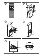
Page 3: ...S1 S2 S3 S4 X X a c d b 2 3 4 5 6 7...
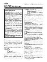
Page 4: ...c a b a c b 8 9 10 11 12...
Page 7: ......